
User`s manual


8
English
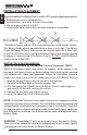
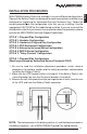
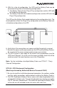
5. Connect a # 8 gauge wire from the UPS's positive (+) terminal to the Battery
Pack's positive (+) terminal. Connect a # 8 gauge wire from the UPS's
negative (-) terminal to the Battery Pack's negative terminal. Verify that the
polarity is correct. Not all of the Battery Packs come with connecting wires.
The minimum wire size for these hardwire connections is a # 8 gauge wire.
A safety earth ground wire may be attached from the UPS's chassis to the
Battery Pack's chassis, but it is not required.
6. Verify that all the connections are secure and that the polarity is correct.
7. Reinstall the cover and the cover plates, on the UPS and the Battery Pack(s).
Be sure that all the cover and cover plate screws are installed.
8. The UPS system is now ready for the normal start-up procedure (see the
UPS User's Manual). On all the units that were installed, check that all the
switches and all the circuit breakers are in the ON position.
Note: For the installation of multiple Battery Packs see STYLE 7: "Daisy
Chained" Configuration.
STYLE 3: Hardwire & Plug and Play Configuration
(Must be performed by Authorized Service Personnel ONLY)
1. Be sure to read the installation placement procedure, caster removal
procedure, the cautions section and the safety precautions section before
installing the Battery Pack(s).
2. Make sure the UPS's power switch is turned off. If the Battery Pack(s) has a
circuit breaker, be sure that the circuit breaker is turned off.
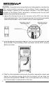
3. Locate the terminal block or the Plug and Play connector on the back of the
UPS. To properly identify the positive connection and the negative
connection of the terminal block or the Plug and Play connector, refer to the
Installation Section in the UPS User's Manual.
4. To locate the terminal block or the Plug and Play connector on the Battery
Pack(s): The terminal block on some models of Battery Packs has an
access panel on the rear panel of the Battery Pack. If the Battery Pack(s)
has no access panel, the terminal block is on the inside of the Battery
Pack(s); the top cover will have to be removed. The Plug and Play connector
cable comes out of the back panel of the Battery Pack. There is a self-stick
protective strip over the contacts of the connector.
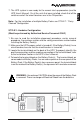
NOTE: The red connector is the battery positive (+) and the black connector is
the battery negative (-) on all MINUTEMAN Plug & Play configurations.
WARNING: Use extreme CAUTION when the cover of the Battery
Pack is removed. There is a danger of Electrical Shock from the
batteries.