
User`s manual

15
English
11. Verify that all the connections are secure and that the polarity is correct.
12. Plug the Battery Pack's power cord back into the AC outlet and turn the
circuit breaker ON.
13. The UPS system is now ready for the normal start-up procedure (see the
UPS User's Manual). On all the units that were installed, check that all
the switches and all the circuit breakers are in the ON position.
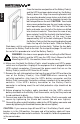
1. Be sure to read the installation placement procedure, the cautions section
and the safety precautions section before installing the Battery Pack(s).
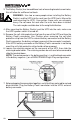
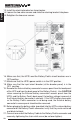
2. The circuit breaker on the back panel of the battery pack(s) turns the battery
voltage OFF and ON.
3. The red connector is the battery positive (+) and the black connector is the
battery negative (-) on all MINUTEMAN MCP-E configurations.
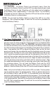
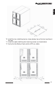
4. The MCP-E series can be installed in two different configurations:
A. Tower and B. Rackmount.
Use CAUTION: the Battery Pack(s) and the UPS are extremely heavy.
Once the location of the Battery Pack(s) and the UPS have been
determined, verify that the Battery Pack and the UPS are stable.
Note: For the installation of multiple Battery Packs see STYLE 7: "Daisy
Chained" Configuration.
1. Make sure that both the Battery Pack's circuit breaker and UPS's power
switch are in OFF position. Unplug all the equipment that is plugged into the
UPS's output receptacles. Disconnect the power cord on the UPS from the
AC outlet.
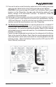
2. Remove the External battery connector's access panel from the back panel
of the UPS and from the back panel of the Battery Pack(s). Use CAUTION
when removing the External battery connector's access panel from the UPS's
and the Battery Pack's back panel; the battery voltage is present at the
External battery connector's contacts. If the UPS's battery connector or the
Battery Pack's connector is not being used, the External battery connector's
access panel should not be removed.
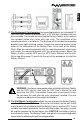
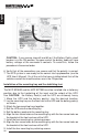
3. Before plugging the battery cable (provided) into the UPS's external battery
connector or the Battery Pack's connector, verify that they mate red to red
and black to black.
4. Connect one end of the Battery Cable to the Battery Pack's connector and
secure by tightening the strain relief screw (do not over tighten).
5. Connect the other end of the battery cable to the UPS's battery connector
and secure by tightening the strain relief screw (do not over tighten).
A. The Tower Configuration
STYLE 6: MCP-E Series Configuration
(Must be performed by Authorized Service Personnel ONLY)