
User`s manual

11
English
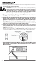
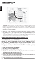
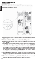
8. Slide the retaining bracket up to secure the battery connector in place and
tighten the retaining screws. Verify that the bracket will not allow the
connector to be pulled out. NOTE: If the retaining bracket will not slide up,
then the connector is not pushed in all the way.
9. Verify that all the connections are secure and that the polarity is correct.
The UPS system is now ready for the normal start-up procedure (see the
UPS User's Manual). On all the units that were installed, check that all the
switches and all the circuit breakers are in the ON position.
10.
Note: For the installation of multiple Battery Packs see STYLE 7: "Daisy
Chained" Configuration.
STYLE 5: Enterprise Universal Series Configuration
(Must be performed by Authorized Service Personnel ONLY)
1. Be sure to read the installation placement procedure, the cautions section
and the safety precautions section before installing the Battery Pack(s).
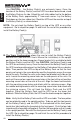
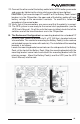
2. The Enterprise Universal Series Battery Packs have an internal charger in
each Battery Pack. The Battery Packs have a DIP switch on the rear panel
to set the input voltage for the chargers at either 115 VAC or 230 VAC.
WARNING! DAMAGE CAN OCCUR IF THE DIP SWITCH IS NOT SET FOR
THE CORRECT INPUT VOLTAGE. To change the input voltage setting:
unplug the Battery Pack's AC power cord, turn the DC circuit breaker off, set
the DIP switch to the desired voltage setting, turn the DC circuit breaker on
and plug the AC power cord into the AC outlet.
WARNING! DO NOT PLUG THE BATTERY PACK'S POWER CORD INTO
THE UPS's OUTPUT RECEPTACLES, DAMAGE TO THE BATTERY PACK'S
INTERNAL CHARGER MAY OCCUR.
3. The circuit breaker on the back panel turns the battery voltage ON and OFF.
To turn the charger OFF, unplug the Battery Pack's AC power cord from the
AC outlet. To turn the charger ON, plug the Battery Pack's AC power cord
into the AC outlet. NOTE: The AC power cord can be "Daisy Chained" up to
a maximum of ten Battery Packs (see "Daisy Chained" Configuration page 21).
4. On the Tower and Wall Mount Configurations, the face plate can be rotated to
read in the upright position. To do so, pull the front panel off the Battery Pack.
On the backside of the front panel, locate four tabs holding the face plate to
the front panel. Push the four tabs inward and the face plate will pop out.
Reinstall the face plate so that it reads in the upright position. Reinstall the
front panel on the Battery Pack.
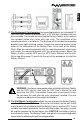
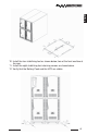
5. The Enterprise Universal Series Battery Packs can be installed in
four different configurations: A. Desk Top, B. Tower, C. Rackmount,
D. Wall Mount.
A. The Desk Top Configuration allows the user to install the monitor, the
UPS and the Battery Pack(s) in one single stack. There are four
self- stick rubber feet provided with the Battery Pack(s) and the UPS.
The four rubber feet can be installed on the bottom side of the Battery
Pack(s) and the UPS (see the UPS User's Manual for installation).