BATTERY PACK User's Manual
English TABLE OF CONTENTS MINUTEMAN BATTERY PACK'S USER'S MANUAL 1. 2. Introduction Installation Installation Placement Caster Removal Installation Procedures Style: 1 Plug and Play Configuration Style: 2 Hardwire Configuration Style: 3 Hardwire & Plug and Play Configuration Style: 4 Pro Rackmount Configuration Style: 5 Enterprise Universal Series Configuration Style: 6 MCP-E Series Configuration Style: 7 "Daisy Chained" Configuration 2 3 4 4 5 5 7 8 9 11 15 21 3. Specifications 23 4.
English INTRODUCTION Thank you for purchasing the MINUTEMAN external Battery Pack(s) for your MINUTEMAN Uninterruptible Power Supply (UPS). It has been designed and manufactured to provide many years of trouble free service. The batteries used in the MINUTEMAN series products are sealed, non-spillable, maintenance-free, lead-acid batteries, with the electrolyte completely absorbed in the plates and separator material.
voltages. DO NOT attempt to disassemble the unit. These Battery Packs contain no user serviceable parts. Repairs and battery replacement must be performed by AUTHORIZED SERVICE PERSONNEL ONLY. RECEIVING INSPECTION Upon receipt of the Battery Pack(s), check the outer packing for any external damage that may have been caused by the carrier. After removing the MINUTEMAN Battery Pack from its carton, inspect the Battery Pack again for any damages that may have occurred in shipping.
English INSTALLATION PLACEMENT Select the location of the Battery Pack(s) and the UPS using the following precautions: 1. Avoid locations near heating devices. 2. Avoid locations near water or excessive humidity. 3. Do not expose to direct sunlight. 4. Route power cords where they cannot be walked on or damaged. The Battery Pack(s) and the UPS must be placed on a level smooth surface. The Battery Packs cannot be stacked more than 4 units high.
MINUTEMAN Battery Packs are available in several different configurations. Some of the Battery Packs are designed for quick connections and others are designed for hardwiring by Authorized Service Personnel Only. Follow the correct procedure for the configuration style that you are installing. Use the appropriate CAUTIONS for the model being installed. If you are unsure of the configuration style that you have or have a question about the procedure, please contact the MINUTEMAN Technical Support Department.
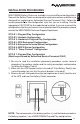
English CAUTION: Use caution when removing the self-stick protective strip from the UPS's external battery connector and the Battery Pack's connector; the battery voltage is present at the connector's contacts. If the UPS's battery connector or the Battery Pack's connector is not being used, the self-stick protective strip should not be removed. 4. Loosen the retaining screws on the rear panel of the UPS, then slide the retaining bracket down.
Note: For the installation of multiple Battery Packs see STYLE 7: "Daisy Chained" Configuration. STYLE 2: Hardwire Configuration (Must be performed by Authorized Service Personnel ONLY) 1. Be sure to read the installation placement procedure, caster removal procedure, the cautions section and the safety precautions section before installing the Battery Pack(s). 2. Make sure the UPS's power switch is turned off. If the Battery Pack(s) has a circuit breaker, be sure that the circuit breaker is turned off. 3.
English 5. Connect a # 8 gauge wire from the UPS's positive (+) terminal to the Battery Pack's positive (+) terminal. Connect a # 8 gauge wire from the UPS's negative (-) terminal to the Battery Pack's negative terminal. Verify that the polarity is correct. Not all of the Battery Packs come with connecting wires. The minimum wire size for these hardwire connections is a # 8 gauge wire. A safety earth ground wire may be attached from the UPS's chassis to the Battery Pack's chassis, but it is not required.
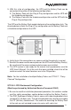
The UPS and the Battery Pack models determine the configuration style. The drawing below reflects the Plug & Play configuration on the Battery Pack and a Hardwire configuration on the UPS. 6. Verify that all the connections are secure and that the polarity is correct. 7. Reinstall the cover and the cover plates on the UPS and the Battery Pack(s). Be sure that all the cover and cover plate screws are installed. 8. The UPS system is now ready for the normal start-up procedure (see the UPS User's Manual).
English English 3. The Battery Pack(s) has two additional sets of mounting bracket screw holes, this will allow for a different set back. WARNING: Use two or more people when installing the Battery Pack(s) and the UPS into the rack (see the UPS User's Manual for rack mounting the UPS). Use caution; these units are extremely heavy. Do not move the rack after the units have been installed. The rack maybe unstable due to the weight distribution. 4.
1. Be sure to read the installation placement procedure, the cautions section and the safety precautions section before installing the Battery Pack(s). 2. The Enterprise Universal Series Battery Packs have an internal charger in each Battery Pack. The Battery Packs have a DIP switch on the rear panel to set the input voltage for the chargers at either 115 VAC or 230 VAC. WARNING! DAMAGE CAN OCCUR IF THE DIP SWITCH IS NOT SET FOR THE CORRECT INPUT VOLTAGE.
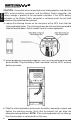
English Use CAUTION: the Battery Pack(s) are extremely heavy. Once the location of the Battery Pack(s) and the UPS have been determined, stand the Battery Pack on its side. Attach the self-stick rubber feet to the bottom of the Battery Pack, approximately 2" from each corner. Lay the Battery Pack down on the four rubber feet. Stack the UPS and the monitor on top of the Battery Pack(s) as shown below. NOTE: Do not stack the Battery Pack(s) on top of the UPS or any other equipment.
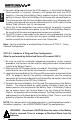
English C. The Rackmount Configuration has mounting brackets for a standard 19" (46.5cm) rack. Mounting brackets to fit a 23" (59.2cm) standard rack are also available. The screws for mounting the Battery Pack(s) to the rack are not included (screw size varies with rack size). The installation of the mounting brackets, is as follows: The Rackmount kit includes two mounting brackets and eight retaining screws.
English Once the location and position of the Battery Pack(s) and the UPS have been determined, lay the Battery Pack(s) down flat. Align the mounting bracket with the mounting bracket screw holes and attach with the retaining screws. Use the template to mark the bolt hole position on the wall. CAUTION: You should always were protective gear for your hands and eyes when operating power tools. Drill the holes for the bolts and make sure that all of the holes are drilled into structural material.
Note: For the installation of multiple Battery Packs see STYLE 7: "Daisy Chained" Configuration. STYLE 6: MCP-E Series Configuration (Must be performed by Authorized Service Personnel ONLY) 1. Be sure to read the installation placement procedure, the cautions section and the safety precautions section before installing the Battery Pack(s). 2. The circuit breaker on the back panel of the battery pack(s) turns the battery voltage OFF and ON. 3.
English CAUTION: If you reverse steps #4 and #5 or if the Battery Pack's circuit breaker is in the ON position, the open end of the battery cable will have battery voltage at the connector's contacts. To avoid this, follow the procedure in the correct order. 6. Verify that all the connections are secure and that the polarity is correct. 7. The UPS system is now ready for the normal start-up procedure (see the UPS User's Manual).
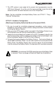
English 10. Install the four stabilizing feet as shown below, two at the front and two at the rear. 11. Install the eight stabilizing feet retaining screws as shown below. 12. Verify that the Battery Pack and the UPS are stable.
English 13. Install the retaining bracket as shown below. 14. Loosen the two cover screws and slide the retaining bracket into place. 15. Retighten the two cover screws. 16. Make sure that, the UPS's and the Battery Pack's circuit breakers are in OFF position. 17. Make sure that the UPS's power switch is in the OFF position. 18. Make sure that the input circuit breaker (at the breaker panel) is in the OFF position. 19.
B. The Rackmount Configuration has mounting brackets for a standard 19" (46.5cm) rack. Mounting brackets to fit a 23" (59.2cm) standard rack are also available. The screws for mounting the Battery Pack(s) to the rack are not included (screw size varies with rack size). The installation of the mounting brackets is as follows: Locate the mounting bracket screw holes on the side panels of the Battery Pack, at the front of the Battery Pack.
English WARNING: Use two or more people when installing the Battery Pack(s) and the UPS into the rack (see the UPS User's Manual for rack mounting the UPS). Use caution; these units are extremely heavy. Do not move the rack after the units have been installed. The rack may be unstable due to the weight distribution. 1. Make sure that the circuit breakers on both the UPS and the Battery Pack(s) are in OFF position. 2. Make sure that the UPS's power switch is in the OFF position. 3.
"Daisy Chained" means hooking one Battery Pack to another Battery Pack to another Battery Pack; this chain could go on indefinitely. Follow the steps below to Daisy Chain the Battery Packs. 1. Be sure to read the installation placement procedure, the cautions section, the safety precautions section and the Configuration Style for your Battery Pack before Daisy Chaining the Battery Pack(s). 2. Make sure that all the Battery Pack's circuit breakers and UPS's power switch, are in OFF position.
English 11. After the installation of all the Battery Packs is complete, verify that all the connections are secure and that the polarity is correct. Verify that all covers, access panels, retaining brackets and their screws are installed. 12. The UPS system is now ready for the normal start-up procedure (see the UPS User's Manual).
English SPECIFICATIONS ! BATTERY PACK MODEL # BPX48V17 BP120V13 BP144V13 BP192V17 BP24V10 BP24V20 BP24V34A BP48V10 BP48V13 BP48V17 BP48V34 BP60V17A CP3BP1 CP6BP1 CP6BP4 CPR3BP3 EBP1 EBP2 EBP3 EBP4 EBP3000LT MCPBP1 MCPBP2 MCPBP3 MCP BP1000 MCP BP2000 MCP BP3000 MCP BP5000 MCP BP7000 MCP BP1000RM MCP BP2000RM MCP BP3000RM PROBPr1 XRTBP1 XRTBP3 BATTERY TYPE 12V18AH 12V7.2AH 12V7.2AH 12V18AH 6V10AH 6V10AH 12V18AH 6V10AH 12V7.2AH 12V18AH 12V18AH 12V18AH 12V7.2AH 12V25AH 12V7.2AH 12V7.2AH 12V7.
English BATTERY PACK MODEL # CK1-2030X-240 CK1-2035X-240 CK1-2050XL-240 CK3-2065-240 CK3-2080X-240 CK3-2090X-240 CK3-20110X-240 CK3-20150X-240 CK4-4065-240 CK4-4080X-240 CK4-4090X-240 CK4-40100X-240 CK4-40110X-240 CK4-40120X-240 CK4-40150X-240 BATTERY TYPE 12V30AH 12V35AH 12V50AH 12V65AH 12V80AH 12V90AH 12V110AH 12V150AH 12V65AH 12V80AH 12V90AH 12V100AH 12V110AH 12V120AH 12V150AH BATTERY QUANTITY 20 20 20 20 20 20 20 20 40 40 40 40 40 40 40 BATTERY PART # 37000011 37000013 37000014 37000016 XXXXXXXX 370
English " HOT-SWAPPABLE BATTERY REPLACEMENT SAFETY PRECAUTIONS Read this manual carefully before installing the Battery Pack(s) or replacing the batteries. All instructions and warnings should be followed during the installation, operation and the maintenance of the Battery Pack(s). Do not attempt to disassemble the unit; there are no user serviceable parts.
English CAUTIONS When replacing the batteries in the Battery Pack(s), the following precautions should be followed: 1. Turn off the equipment plugged into the UPS, then turn off the UPS. 2. Before removing the cover screws, disconnect the equipment from the output receptacles, the power cord from the AC outlet and the battery connectors from the UPS. 3. Remove watches, rings and any other metallic jewelry before servicing the Battery Pack(s) or the UPS. 4. Use tools with insulated handles. 5.
English 3. Disconnect the battery cable from the UPS's external battery connector. 4. Remove the front panel of the Battery Pack. 5. Remove the four retaining screws from the battery tray retaining bracket. 6. Disconnect the mating, red and black, battery connectors. 7. Grasp the battery tray handle and gently pull the battery tray out. Use CAUTION: the battery tray is extremely heavy. 8. Remove the battery jumper wires, the battery connector and the batteries. 9.
English SERVICE POLICY 1. Use the Troubleshooting Guide in the UPS User's Manual to eliminate obvious causes. 2. Verify there are no circuit breakers tripped and that the Battery Pack's power cord (not on all models) is plugged into the AC outlet. A tripped circuit breaker is the most common problem. 3. If you are not getting the expected runtime, charge the Battery Pack(s) for 8 hours then retest. 4. Call your dealer for assistance. If you cannot reach your dealer, or if they cannot resolve the problem.
English # LIMITED PRODUCT WARRANTY Para Systems Inc. (Para Systems) warrants this equipment, when properly applied and operated within specified conditions, against faulty materials or workmanship for a period of three years from the date of original purchase by the end user. For equipment sites within the United States and Canada, this warranty covers repair or replacement of defective equipment at the discretion of Para Systems. Repair will be from the nearest authorized service center.
Para Systems, Inc. 1455 LeMay Dr. Carrollton, TX 75007 Phone: (972) 446-7363 Fax: (972) 446-9011 QuickFax Info System: 1-800-263-3933 Internet: www.minutemanups.com P/N 34000011-Rev.