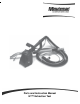
Parts and Instruction Manual ET™ Extraction Tool
This manual is furnished with each new MINUTEMAN ET™ Extraction Tool. This provides the necessary operating and preventive maintenance instructions. Operators must read and understand this manual before operating or servicing this machine. This machine was designed to give you excellent performance and efficiency. For best results and minimal cost, please follow the general guidelines below: · Operate the machine with reasonable care.
Parts and Instruction Manual
Table of Contents IMPORTANT SAFETY INSTRUCTIONS ....................................................................... 1 INSPECTION ................................................................................................................. 2 ELECTRICAL ................................................................................................................ 2 Model C46300-00 (115V) ..........................................................................................
FOR COMMERCIAL USE ONLY IMPORTANT SAFETY INSTRUCTIONS When using an electrical appliance, basic precautions should always be followed, including the following: READ ALL INSTRUCTIONS BEFORE USING WARNING - To reduce the risk of fire, electric shock, or injury: • Do not leave appliance when plugged in. Unplug from outlet when not in use and before servicing. WARNING To reduce the risk of electrical shock, do not expose to rain. Store indoors. • Do not immerse.
INSPECTION Carefully unpack and inspect your machine for shipping damage. Each unit is tested and thoroughly inspected before shipment, and any damage is the responsibility of the delivery carrier who should be notified immediately. ELECTRICAL - Model C46300-00 (115V) This machine is designed to operate on a standard 15 amp. 115 volt, 60 hz, AC circuit. Voltages below 105 volts AC or above 125 volts AC could cause serious damage to the motor.
USER MAINTENANCE INSTRUCTIONS All service and repair should be performed by qualified vacuum service representative or electrician. No user serviceable components are employed in the electrical assembly. No lubrication of the motor is required. DAILY MAINTENANCE 1. The powerhead should be cleaned daily. Flush pumping system with 1 gallon of clean water after use. 2. Check and clean vacuum inlet and solution inlet daily. 3. Brushes should be cleaned after each use. 4.
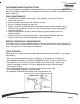
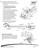
OPERATING INSTRUCTIONS 1. Follow the operating instructions as described in the “Gotcha!” (or the Ambassador) Parts and Instruction Manual. 2. Connect the vac/solution hose assembly to the “Gotcha!” (see fig. 1) or the Ambassador (see fig. 2A). FIG. 1 3. Plug power cord into the receptacle located at the lower back portion of the machine. (see fig. 2 and fig. 2A). 4. For the brush and spray to operate, the switch on the “Gotcha!” (see fig.
EXTENSION WAND INSTALLATION 1. Detach power cord from the trigger guard and the cable clip. 2. Disengage powerhead from handle assembly by depressing the burgundy locking button and disconnecting coupling 1. (see fig. 3). 3. Insert the stainless steel extension wand curved end, (see fig. 4) into the powerhead assembly until the locking button is engaged. Connect coupling 2 to the hose assembly on the powerhead. 4. At the other end of the extension wand, (fig.
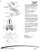
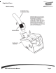
Exploded Views Main Assembly Parts and Instruction Manual Page 6
Head Assembly ITEM PART NO 1 2 3 4 5 6 7 7A 8 9 10 11 12 13 14 15 16 16A 17 18 19 450260 715339 742298 450274 715336 711158 450287 450288 450273 850042 711163 450264 450269 450276 712822 712764 742370 742373 450285 711551 710305 QTY 1 1 1 1 1 2 1 1 1 1 2 1 1 1 2 2 1 1 2 3 3 DESCRIPTION ITEM Powerhead Assembly Decal, Switch Switch, 3-Position Knob Assembly Decal, Brush Removal SCR-Hi/Lo #7-19 x 3/8 Brush Assembly, Carpet Brush Assembly, Upholstery Pulley Bearing 6000 Sealed SCR-Hi/Lo #10-16 x ½ Belt
Handle Assembly ITEM 1 2 3 4 5 6 7 8 9 10 11 12 13 14 15 Parts and Instruction Manual PART NO 450256 450258 450249 711163 450257 390053 711803 390063 712323 450267 450265 450221 450261 450262 833725 QTY 1 1 1 5 1 1 1 2 1 1 3 1 1 1 1 DESCRIPTION Pick-up Tube Trigger Guard, Right Spotter Hose Assembly Complete SCR-Hi/Lo #10-16 x ½ Trigger Guard, Left Trigger Solution Valve Cotter Pin .06 x .75 Grove Stud Rd. Hd. #2427 WSR-Flat .195 x .281 x .
Minuteman International Made Simple Commercial Limited Warranty Minuteman International, Inc. warrants to the original purchaser/user that the product is free from defects in workmanship and materials under normal use. Minuteman will, at its option, repair or replace without charge, parts that fail under normal use and service when operated and maintained in accordance with the applicable operation and instruction manuals.