MOTION CONTROL NextMove PCI Motion Controller Installation Manual 3/02 MN1903
Contents 1 General Information . . . . . . . . . . . . . . . . . . . . . . . . . . . . . . . . . 1-1 2 Introduction . . . . . . . . . . . . . . . . . . . . . . . . . . . . . . . . . . . . . . . . 2-1 2.1 NextMove PCI features . . . . . . . . . . . . . . . . . . . . . . . . . . . . . . . . . . 2-1 2.2 Receiving and inspection . . . . . . . . . . . . . . . . . . . . . . . . . . . . . . . . 2-3 2.2.1 2.3 3 Units and abbreviations . . . . . . . . . . . . . . . . . . . . . . . . . . . . . . . . . .
.6 CAN Connections . . . . . . . . . . . . . . . . . . . . . . . . . . . . . . . . . . . . . . . 4-20 4.6.1 4.6.2 4.7 5 Emulator connection . . . . . . . . . . . . . . . . . . . . . . . . . . . . . . . . . . . . . . . . . . . . 4-23 Reset states . . . . . . . . . . . . . . . . . . . . . . . . . . . . . . . . . . . . . . . . . . . 4-23 4.8.1 4.9 4-21 4-22 Other I/O . . . . . . . . . . . . . . . . . . . . . . . . . . . . . . . . . . . . . . . . . . . . . . 4-23 4.7.1 4.8 CAN1 (CANopen) - X17 . . .
6 Troubleshooting . . . . . . . . . . . . . . . . . . . . . . . . . . . . . . . . . . . . 6-1 6.1 Introduction . . . . . . . . . . . . . . . . . . . . . . . . . . . . . . . . . . . . . . . . . . . . 6.1.1 6.1.2 6.2 NextMove PCI indicators . . . . . . . . . . . . . . . . . . . . . . . . . . . . . . . . . 6.2.1 6.2.2 6.2.3 7 Problem diagnosis . . . . . . . . . . . . . . . . . . . . . . . . . . . . . . . . . . . . . . . . . . . . . . SupportMet feature . . . . . . . . . . . . . . . . . . . . . . . . . .
iv Contents MN1903
1 General Information 1 LT0166A00 Copyright Baldor (c) 2002. All rights reserved. This manual is copyrighted and all rights are reserved. This document or attached software may not, in whole or in part, be copied or reproduced in any form without the prior written consent of BALDOR. BALDOR makes no representations or warranties with respect to the contents hereof and specifically disclaims any implied warranties of fitness for any particular purpose.
Safety Notice Only qualified personnel should attempt the start-up procedure or troubleshoot this equipment. This equipment may be connected to other machines that have rotating parts or parts that are controlled by this equipment. Improper use can cause serious or fatal injury. Only qualified personnel should attempt to start-up, program or troubleshoot this equipment.
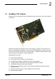
2 Introduction 2 2.1 NextMove PCI features NextMove PCI is a high speed multi-axis intelligent motion controller for use in PCI bus based PC systems. NextMove PCI features the MintMT motion control language. MintMT is a structured form of Basic, custom designed for stepper or servo motion control applications. It allows you to get started very quickly with simple motion control programs. In addition, MintMT includes a wide range of powerful commands for complex applications.
Included with NextMove PCI is the Baldor Motion Toolkit CD. This contains a number of utilities and useful resources to get the most from you MintMT controller. These include: H Mint WorkBench v5 This is the user interface for communicating with the NextMove PCI. Installing Mint WorkBench will also install firmware for NextMove PCI. H PC Developer Libraries These include ActiveX interfaces that allow PC applications to be written that communicate with the NextMove PCI.
2.2 Receiving and inspection When you receive your NextMove PCI, there are several things you should do immediately: 1. Check the condition of the packaging and report any damage immediately to the carrier that delivered your NextMove PCI. 2. Remove the NextMove PCI from the shipping container but do not remove its anti-static bag until you are ready to install it. The packing materials may be retained for future shipment. 3.
2.3 Units and abbreviations The following units and abbreviations may appear in this manual: V ............... W .............. A ............... Ω ............... µF . . . . . . . . . . . . . . pF . . . . . . . . . . . . . . mH . . . . . . . . . . . . . Volt (also VAC and VDC) Watt Ampere Ohm microfarad picofarad millihenry Φ............... ms . . . . . . . . . . . . . . µs . . . . . . . . . . . . . . ns . . . . . . . . . . . . . . phase millisecond microsecond nanosecond Kbaud . . . . . . . . . . .
3 Basic Installation 3 3.1 Introduction You should read all the sections in Basic Installation. It is important that the correct steps are followed when installing the NextMove PCI. This section describes the mechanical and electrical installation of the NextMove PCI. 3.1.
3.2 Location requirements It is essential that you read and understand this section before beginning the installation. CAUTION: To prevent equipment damage, be certain that input and output signals are powered and referenced correctly. CAUTION: To ensure reliable performance of this equipment be certain that all signals to/from the NextMove PCI are shielded correctly.
3.3 Installation NextMove PCI can be installed into an AT style personal computer that has a free 7 inch PCI card slot. The Baldor Motion Toolkit CD supports the following operating systems: Windows 95, Windows 98, Windows ME, Windows NT4 and Windows 2000. 3.3.1 Installing the NextMove PCI card CAUTION: Before touching the card, be sure to discharge static electricity from your body and clothing by touching a grounded metal surface. Alternatively, wear an earth strap while handling the card. 1. 2. 3. 4.
3-4 Basic Installation MN1903
4 Input / Output 4 4.1 Outline This section describes the digital and analog input and output capabilities of the NextMove PCI. The following conventions will be used to refer to the inputs and outputs: I/O . . . . . . . . . . . . . . DIN . . . . . . . . . . . . . DOUT . . . . . . . . . . . AIN . . . . . . . . . . . . . AOUT . . . . . . . . . . .
4.2.
Pin Signal Pin Signal 29 Direction Output 1 79 Direction Output 3 30 Step Output 3 80 DOUT11 31 DOUT10 81 USR V+ 32 DOUT9 82 DOUT8 33 DOUT7 83 USR V+ 34 DOUT6 84 DOUT5 35 DOUT4 85 CGND 36 DOUT3 86 DOUT2 37 DOUT1 87 CGND 38 DOUT0 88 Common2 39 DIN19 89 DIN17 40 DIN18 90 DIN16 41 DIN15 91 DIN13 42 DIN14 92 DIN12 43 DIN11 93 DIN9 44 DIN10 94 DIN8 45 DIN7 95 DIN5 46 DIN6 96 DIN4 47 DIN3 97 DIN1 48 DIN2 98 DIN0 49 Common1 99 R
4.3 Analog I/O The NextMove PCI provides: H Four 12-bit resolution analog inputs. The inputs are available on connector X6 on the NextMove PCI Breakout module. H Four 14-bit resolution analog outputs. The outputs are available on connector X7 on the NextMove PCI Breakout module. Sections 4.3.1 to 4.3.2 describe each analog input and output.
4.3.1 Analog inputs - X6 12 1 Location Breakout module, connector X6 Pin Name MintMT keyword / description 1 AGND Analog ground 2 AIN0+ 3 AIN0- 4 AIN1+ 5 AIN1- 6 Shield Shield connection 7 AGND Analog ground 8 AIN2+ 9 AIN2- 10 AIN3+ 11 AIN3- 12 Shield AIN0 AIN1 AIN2 AIN3 Shield connection Description Single ended or differential inputs Voltage range: software selectable 0-5V, ±5V, 0-10V, ±10V Resolution: 12-bit with sign (accuracy ±4.
Breakout module X6 AIN0- 3 AIN0+ 2 AGND 1 NextMove PCI 100 pin cable + + MintMT ADC.0 Figure 1 - Analog input wiring, AIN0 shown For differential inputs connect input lines to AIN+ and AIN-. Leave AGND unconnected. For single ended inputs, connect signal to AIN+. Connect signal ground to AIN- and AGND.
4.3.
4.4 Digital I/O There are a total of 20 general purpose digital inputs. Inputs can be configured in MintMT for any of the following functions: H forward limit (end of travel) input on any axis H reverse limit (end of travel) input on any axis H home input on any axis H drive error input on any axis. The inputs use two separate common connections. This can be useful for separating inputs which are active low from others which are active high.
Inputs can be shared between axes, and are programmable in MintMT (using the keywords INPUTACTIVELEVEL, INPUTMODE, INPUTPOSTRIGGER and INPUTNEGTRIGGER) to determine their active level and if they should be edge triggered. Four of the inputs, DIN0-DIN3, are fast position latch inputs. There are a total of 12 general purpose digital outputs. An output can be configured in MintMT as a general purpose output, a drive enable output or a general error output.
4.4.1 Digital inputs - X1 Location 12 1 Breakout module, connector X1 Pin Name MintMT keyword / description Common 1 Shield Shield connection 2 DIN12 INX.12 3 DIN13 INX.13 4 DIN14 INX.14 5 DIN15 INX.15 6 DIN16 INX.16 7 DIN17 INX.17 8 DIN18 INX.18 9 DIN19 INX.19 10 Shield Shield connection 11 - (NC) 12 Common2 Common connection Common2 Description Eight general purpose optically isolated AC digital inputs.
The inputs are conditioned using low pass RC filters and Schmitt trigger buffers. If an input is configured as edge triggered, the triggering pulse must have a duration of at least 1ms (one software scan) to guarantee acceptance by MintMT. Voltages below 2V are considered as 0V. The use of shielded cable for inputs is recommended. Active high: The digital inputs will be active when a voltage of +24VDC (±20%) is applied to them and will sink a maximum of 8mA each.
4.4.3 Digital inputs - X3 Digital inputs DIN0 to DIN3 can be used as high speed position latches. The fast position inputs are routed through a programmable cross-point switch which allows any input to cause the position of any combination of axes to be captured (by the hardware) within 1µs. Special MintMT keywords (beginning with the letters FAST...) allow specific functions to be performed as a result of fast position inputs becoming active.
4.4.4 Digital outputs - X4 12 1 Location Breakout module, connector X4 Pin Name MintMT keyword / description 1 Shield Shield connection 2 DOUT6 OUTX.6 3 DOUT7 OUTX.7 4 DOUT8 OUTX.8 5 DOUT9 OUTX.9 6 DOUT10 OUTX.10 7 DOUT11 OUTX.11 8 - (NC) - (NC) 10 9 Shield Shield connection 11 USR V+ Customer power supply 12 CGND Customer power supply ground Description Six general purpose optically isolated digital outputs.
USR V+ NextMove PCI Breakout module OUTX.6 X4 11 Output module 100 pin cable Output load 2 DOUT6 12 CGND Figure 6 - Digital output circuit with optional ‘NPN’ current sinking module - DOUT6 shown 4.4.5 Digital outputs - X5 12 1 Location Breakout module, connector X5 Pin Name MintMT keyword / description 1 Shield Shield connection 2 DOUT0 OUTX.0 3 DOUT1 OUTX.1 4 DOUT2 OUTX.2 5 DOUT3 OUTX.3 6 DOUT4 OUTX.4 7 DOUT5 OUTX.
4.5 Other I/O 4.5.
4.5.2 Encoder input frequency The maximum encoder input frequency is affected by the length of the encoder cables. The theoretical maximum frequency is 7.5 million quadrature counts per second. This is equivalent to a maximum frequency for the A and B signals of 1.87MHz. However, the effect of cable length is shown in Table 3: Frequency Maximum cable length meters feet 1.3MHz 2 6.56 500kHz 10 32.8 250kHz 20 65.6 100kHz 50 164.0 50kHz 100 328.1 20kHz 300 984.2 10kHz 700 2296.
4.5.3 Power - X9 10 Location Pin 1 Breakout module, connector X9 Name 1 Vcc 2 Vcc 3 Encoder V+ 4 Encoder V+ 5 GND 6 GND 7 USR V+ 8 USR V+ 9 CGND 10 CGND Description +5V supply source from the host PC Power to the encoder connectors Digital ground from the host PC Customer power supply Customer power supply ground Description Connection point for customer power supply USR V+. Also used to route power to encoders.
4.5.
4.5.
4.6 CAN Connections 5&6 1&2 CAN (Controller Area Network) is a 1Mb/s local area network. Two CAN channels are supported by NextMove PCI - CANopen and Baldor CAN. Access to both channels is configured by a 10-pin 2mm pin header, J11, mounted along the top edge of the NextMove PCI card. Jumpers link pin pairs 1 and 2, 3 and 4, 5 and 6, 7 and 8. These jumpers route the CAN signals to the breakout module and only need to be removed if you are connecting a CAN Bracket card.
H Terminators must only be fitted at both ends of the network, not at intermediate nodes. H The 0V connection of all of the nodes on the network must be tied together through the CAN cabling. This ensures that the CAN signal levels transmitted by NextMove PCI or CAN peripheral devices are within the common mode range of the receiver circuitry of other nodes on the network. 4.6.1 CAN1 (CANopen) - X17 CANopen connections are made using the breakout module connector X17.
4.6.2 CAN2 (Baldor CAN) - X18 Baldor CAN connections are made using the breakout module connector X18. Location Breakout module, connector X18 Pin Name 1 8 Description 1 - (NC) 2 - (NC) 3 - (NC) 4 CAN2 0V Ground/earth reference for CAN signal 5 CAN2 V+ CAN remote node power V+ (12-24V) 6 (NC) - 7 CAN2+ CAN channel 2 positive 8 CAN2- CAN channel 2 negative Description Baldor proprietary CAN interface using a RJ45 connector.
4.7 Other I/O 4.7.1 Emulator connection An 11-pin footprint on the rear of the card marked ‘ICE’ provides access to the processor for boundary scan emulation. To connect the Texas Instruments emulator pod, a two row 12-pin 0.1in pitch surface mount pin header with pin 8 missing must be fitted. The connections are those specified by Texas Instruments. See the ‘MintMT Embedded Programming Guide’ for details on emulator based system debugging. 4.
4.9 Connection summary - minimum system wiring As a guide, Figure 9 shows an example of the typical minimum wiring required to allow the NextMove PCI and a single axis servo amplifier (motor drive) to work together. Details of the connector pins are shown in Table 4.
The pin connections in the example are described below: Breakout module connector Pin Name of signal 1 Demand0 2 AGND X12 - Encoder X1 2 DIN12 12 Common2 7 6 X7 X8 Function Command signal for axis 0 Connection on drive (Note: drive may be labelled differently) Demand+ input Demand- input Position feedback Encoder out (or direct from motor) Error input Error output Relay COM Common connection of relay Enable input Relay NO Normally open connection of relay Amplifier/Digital Grou
4-26 Input / Output MN1903
5 Operation 5 5.1 Introduction The software provided includes a number of applications and utilities to allow you to configure, tune and program the NextMove PCI. If you do not have experience of software installation or Windows applications you will need to seek further assistance for this stage of the installation. The CDROM containing the software can be found inside the rear cover of this manual or separately within the packaging. 5.1.1 Installing the driver software - Windows 95, 98 and ME 1.
5.1.2 Installing the driver software - Windows NT Windows NT does not support ‘plug and play’ so there will be no indication that a new card has been installed. The device driver for NextMove PCI must be installed from the Baldor Motion Toolkit CD. 1. Place the Baldor Motion Toolkit CD into the CDROM drive. The CD should auto-run and display the opening page. If auto-run is disabled, browse the CD and double click the file SETUP.HTM. 2.
5.1.4 Installing WorkBench v5 You will need to install WorkBench v5 to configure and tune the NextMove PCI. 1. Insert the CDROM into the drive. 2. After a few seconds the setup wizard should start automatically. If the setup wizard does not appear, select Run... from the Windows Start menu and type d:\start where d represents the drive letter of the CDROM device. Follow the on-screen instructions to install WorkBench v5. The setup Wizard will copy the files to appropriate folders on the hard drive.
5.1.5 Starting WorkBench v5 1. On the Windows Start menu, select Programs, WorkBench v5, WorkBench v5. WorkBench v5 will start, and the Tip of the Day dialog will be displayed. You can prevent the Tip of the Day dialog appearing next time by removing the check mark next to Show tips at startup. Click Close to continue. 2. In the small opening dialog box, click Start New Project...
3. In the Select Controller dialog, go to the drop down box near the top and select Do not scan serial ports. Click Scan to search for the NextMove PCI. When the search is complete, click ‘NextMove PCI card 0’ and then click Select. 4. A dialog box will appear to tell you that the NextMove PCI currently has no firmware. Click Yes to search for firmware.
5. In the Open dialog, look in the sub folder ‘NextMove PCI’. Select the file with extension ‘.chx’ and click Open to download the firmware. The firmware will be downloaded to the NextMove PCI. (A dialog box may be displayed to tell you that WorkBench v5 has detected the new firmware. Click OK to continue). WorkBench v5 reads back data from the NextMove PCI. When this is complete, Fine-tuning mode is displayed. This completes the software installation.
5.2 WorkBench v5 WorkBench v5 is a fully featured application for programming and controlling the NextMove PCI. The main WorkBench window contains a menu system, the Toolbox and other toolbars. Many functions can be accessed from the menu or by clicking a button - use whichever you prefer. Most buttons include a ‘tool-tip’; hold the mouse pointer over the button (don’t click) and its description will appear. 5.2.
5.3 Configuring an axis The NextMove PCI is capable of controlling servo and stepper axes. This section describes the basic setup for both types of axis. Commands typed in the Command window have immediate effect - they do not need to be separately downloaded to the NextMove PCI. 5.3.1 Choosing an axis - 1, 2, 3 and 4 axis cards For the 1, 2, 3 and 4 axis cards, each axis can be configured as either a servo axis or a stepper axis. The factory preset configuration for all the axes is servo.
5.3.3 Selecting a scale MintMT defines all positional and speed related motion keywords in terms of encoder quadrature counts (for servo motors) or steps for stepper motors. The number of quadrature counts (or steps) is divided by the SCALE factor allowing you to use units more suitable for your application. The unit defined by setting a value for scale is called the user unit (uu). Consider a motor with a 1000 line encoder. This provides 4000 quadrature counts for each revolution.
5.3.4 Setting the drive enable output The drive enable output allows NextMove PCI to disable the drive in the event of an error. Each axis can be configured with its own drive enable output, or can share an output with other axes. If an output is shared, an error on any of the axes sharing the output will cause all of them to be disabled. The drive enable output can either be a digital output or the relay. 1. In the Toolbox, click the Digital I/O icon. 2.
4. If you are going to use the relay, drag the grey Relay0 icon to the grey X axis icon on the right of the screen. To configure multiple axes to use the relay, repeat this step for the other axes. If you are using a digital output, drag the bright blue OUT icon to the grey X axis icon on the right of the screen. To configure multiple axes with the same drive enable output, repeat this step for the other axes. 5. Click Apply at the bottom of the screen.
5.4 Servo axis - testing and tuning This section describes the method for testing and tuning a servo axis. To test a stepper axes, go straight to section 5.8. 5.4.1 Testing the drive command output This section tests the operation and direction of the axis command output. It is recommended that the motor is disconnected for this test. 1. Check that the Drive enable button is pressed (down). 2. In the Toolbox, click Application then click the Edit & Debug icon. 3. Click in the Command window. 4.
6. To remove the demand and stop the test, type: STOP.0 This should cause the demand produced at the Demand 0 output to become 0V. 5.4.2 An introduction to closed loop control This section describes the basic principles of closed loop control. If you are familiar with closed loop control go straight to section 5.5.1. When there is a requirement to move an axis, the NextMove PCI control software translates this into a demand output voltage.
This problem is overcome by using a term called Integral gain (KINT). This sums the error over time, so that the motor torque is gradually increased until the positional error is reduced to zero [ like a person gradually pushing harder and harder on your car until they’ve pushed it level with Demand]. However, if there is large load on the motor (it is supporting a heavy suspended weight for example), it is possible for the output to increase to 100% demand.
Figure 11 - The NextMove PCI servo loop MN1903 Operation 5-15
5.5 Servo axis - tuning for current control 5.5.1 Selecting servo loop gains All servo loop parameters default to zero, meaning that the demand output will be zero at power up. Most servo amplifiers can be set to current (torque) control mode or velocity control mode; check that the servo amplifier will operate in the correct mode. The procedure for setting system gains differs slightly for each. To tune an axis for velocity control, go straight to section 5.7.
3. Click in the KPROP box and enter a value that is approximately one quarter of the value of KDERIV. If the motor begins to vibrate, decrease the value of KPROP or increase the value of KDERIV until the vibration stops. Small changes may be all that is necessary. 4. In the Move Type drop down box, check that the move type is set to Step. 5. Click in the Distance box and enter a distance for the step move.
5.5.2 Underdamped response If the graph shows that the response is underdamped (it overshoots the demand, as shown in Figure 12) then the value for KDERIV should be increased to add extra damping to the move. If the overshoot is excessive or oscillation has occurred, it may be necessary to reduce the value of KPROP. Measured position Demand position Figure 12 - Underdamped response 9. Click in the KDERIV and/or KPROP boxes and make the required changes. The ideal response is shown in section 5.5.4.
5.5.3 Overdamped response If the graph shows that the response is overdamped (it reaches the demand too slowly, as shown in Figure 13) then the value for KDERIV should be decreased to reduce the damping of the move. If the overdamping is excessive, it may be necessary to increase the value of KPROP. Demand position Measured position Figure 13 - Overdamped response 10. Click in the KDERIV and/or KPROP boxes and make the required changes. The ideal response is shown in section 5.5.4.
5.5.4 Critically damped response If the graph shows that the response reaches the demand quickly and only overshoots the demand by a small amount, this can be considered an ideal response for most systems. See Figure 14.
5.6 Servo axis - eliminating steady-state errors In systems where precise positioning accuracy is required, it is often necessary to position within one encoder count. Proportional gain, KPROP, is not normally able to achieve this because a very small following error will only produce a small demand for the drive which may not be enough to overcome mechanical friction (this is particularly true in current controlled systems). This error can be overcome by applying integral gain.
5.7 Servo axis - tuning for velocity control Drives designed for velocity control incorporate their own velocity feedback term to provide system damping. For this reason, KDERIV (and KVEL) can be set to zero. Correct setting of the velocity feed forward gain KVELFF is important to get the optimum response from the system. The velocity feed forward term takes the instantaneous velocity demand from the profile generator and adds this to the output block (see Figure 11).
The analog demand output is controlled by a 12-bit DAC, which can create output voltages in the range -10V to +10V. This means a maximum output of +10V corresponds to a DAC value of 2048. The value of KVELFF is calculated by dividing 2048 by the number of quadrature counts per servo loop, so: KVELFF = = 2048 / 200 10.24 5. Click in the KVELFF box and enter the value. The calculated value should give zero following error in normal operation.
9. Using the check boxes below the graph, select the Measured velocity and Demand velocity traces. Demand velocity Measured velocity Figure 15 - Correct value of KVELFF It may be necessary to make changes to the calculated value of KVELFF. If the trace for Measured velocity appears above the trace for Demand velocity, reduce the value of KVELFF. If the trace for Measured velocity appears below the trace for Demand velocity, increase the value of KVELFF. Repeat the test after each change.
5.7.2 Adjusting KPROP The KPROP term can be used to reduce following error. Its value will usually be much smaller than the value used for an equivalent current controlled system. A fractional value, for example 0.1, will probably give the best response. 1. Click in the KPROP box and enter a starting value of 0.1. 2. Click Go. The NextMove PCI will perform the move and the motor will turn. As the soon as the move is completed, WorkBench v5 will download captured data from the NextMove PCI.
Demand position Measured position Figure 16 - Correct value of KPROP The two traces will probably appear with a small offset from each other. Adjust KPROP by small amounts until the two traces appear on top of each other (approximately), as shown in Figure 16.
5.8 Stepper axis - testing This section describes the method for testing a stepper axis. The stepper control is an open loop system so no tuning is necessary. 5.8.1 Testing the drive command output This section tests the operation and direction of the axis command output. It is recommended that the system is initially tested and tuned with the motor shaft disconnected from other machinery. 1. Check that the Drive enable button is pressed. 2. In the Toolbox, click the Edit & Debug icon. 3.
5.9 Digital input/output configuration The Digital I/O window can be used to setup other digital inputs and outputs. 5.9.1 Digital input configuration The Digital Inputs tab allows you to define how each digital input will be triggered and, optionally, if it is to be allocated to a special function, for example the Forward Limit. In the following example, digital input 1 will be set to trigger on a falling edge, and allocated to the forward limit input of axis 0: 1.
4. Now drag the IN1 icon onto the Fwd Limit icon . This will setup IN1 as the Forward Limit input of axis 0. 5. Click Apply to send the changes to the NextMove PCI. Note: If required, multiple inputs can be configured before clicking Apply. 5.9.2 Digital output configuration The Digital Outputs tab allows you to define how each digital output will operate and if it is to be allocated to a drive enable output (see section 5.3.4). Remember to click Apply to send the changes to the NextMove PCI.
5.10 Saving setup information When power is removed from the NextMove PCI all data, including configuration and tuning parameters, is lost. You should therefore save this information in a file, which can be loaded when the card is next used. Alternatively, the information can be included in program files as part of the Startup block. 1. In the Toolbox, click the Edit & Debug icon. 2. On the main menu, choose File, New File. A new program editing window will appear. 3.
4. On the main menu, choose File, Save File. Locate a folder, enter a filename and click Save. 5.10.1Loading saved information 1. In the Toolbox, click the Edit & Debug icon. 2. On the main menu, choose File, Open File... Locate the file and click Open. A Startup block should be included in every Mint program, so that whenever a program is loaded and run the NextMove PCI will be correctly configured. Remember that every drive/motor combination has a slightly different response.
5-32 Operation MN1903
6 Troubleshooting 6 6.1 Introduction This section explains common problems and their solutions. If you want to know the meaning of the LED indicators, see section 6.2. 6.1.1 Problem diagnosis If you have followed all the instructions in this manual in sequence, you should have few problems installing the NextMove PCI. If you do have a problem, read this section first. In WorkBench v5, use the Error Log tool to view recent errors and then check the help file.
6.2 NextMove PCI indicators 6.2.1 Status and CAN LEDs The backplate of the NextMove PCI contains four LEDs. S1 and S2 represent general status information. C1 and C2 are CAN traffic indicators. The LEDs may illuminate red or green and can be continuous or flashing. C1 S1 C2 S2 LED State(s) Meaning All off NextMove PCI is not powered. All red In hardware reset (see section 4.8). All green, cycling In software reset, with no errors (see section 4.8).
6.2.2 Communication If the problem is not listed below please contact Baldor Technical Support. An oscilloscope will be useful for many of the electrical tests described below. Symptom Check Cannot detect NextMove PCI Check that the NextMove PCI driver has been installed. Cannot communicate with the controller. Verify that WorkBench v5 is loaded and that NextMove PCI is the currently selected controller.
Symptom Check Motor runs uncontrollably when controller is switched on and servo loop gains are applied or when a move is set in progress. Motor then stops after a short time. Check that the axis’ corresponding encoder and demand signals are connected to the same axes of motion. Check the demand to the drive is connected with the correct polarity. Check that for a positive demand signal, a positive increase in axis position is seen.
7 Specifications 7 7.1 Introduction This section provides technical specifications of the NextMove PCI 7.1.1 Mechanical specifications Description Value Input power (from host PC) +5V at 1200mA ±12V at 250mA Additional current will be required when powering the encoders from the host PC’s +5V supply. Input power (from customer supply) +12V to +24V at 1200mA Power consumption 15W (PCI card only) Weight Approximately 0.67lb (305g) Nominal overall dimensions Standard 7in PCI card 175mm (6.
7.1.3 Analog outputs (Drive Demand/Command - X7) Description Unit Type Value Bipolar Output voltage range VDC ±10 Output current (max) mA 1 Output DAC resolution bits 14 (includes sign bit) Equivalent resolution mV ±1.22 Update interval Immediate 7.1.
7.1.6 Digital outputs (X4) Description Output current (maximum, each output) Unit mA Update interval Value 50 Immediate 7.1.7 Relay output (X8) Description Unit Value Contacts Normally closed Contact rating (resistive) 1A @ 24VDC or 0.5A @ 125VAC Maximum carrying current A 2 Maximum switching power 62.5VA, 30W Maximum switching voltage 125VAC, 60VDC Maximum switching current Contact resistance (maximum) A mΩ Update interval 1 100 Immediate 7.1.
7.1.9 Stepper outputs (X10 & X11) Description Unit Output type Maximum output frequency Pulse (step) and direction MHz Output voltage Output current Value 3 5V mA 20 max. 7.1.10CANopen interface (X17) Description Unit Signal Channels Bit rate Value 2-wire, isolated 1 Kbit/s Protocol 10, 20, 50, 100, 125, 250, 500, 800, 1000 CANopen 7.1.
A Accessories A A.1 Introduction NextMove PCI is supplied with a software license to control 1, 2 ,3, 4 or 8 axes. Similarly, the NextMove PCI Expansion Card is supplied with a software license to control a further 4 or 8 axes. A license cannot be upgraded. A.1.1 NextMove PCI Expansion card The NextMove PCI Expansion Card is available in 4 or 8 axis variants and provides an additional 20 digital inputs, 12 digital outputs, 4 analog inputs, 4 analog outputs (drive command outputs) and a relay.
A description of the catalog numbers are shown in the following table: Catalog number Description PCI002-501 NextMove PCI Expansion card with PNP digital outputs, 4 axis PCI002-502 NextMove PCI Expansion card with PNP digital outputs, 8 axis PCI002-503 NextMove PCI Expansion card with NPN digital outputs, 4 axis PCI002-504 NextMove PCI Expansion card with NPN digital outputs, 8 axis OPT025-504 Expansion interconnect card to connect NextMove PCI to one expansion card OPT025-505 Dual expansion in
A.1.3 Expansion card status LEDs The backplate of the NextMove PCI Expansion card contains two LEDs, S1 and S2. These represent general status information. The LEDs may illuminate red or green and can be continuous or flashing. Expansion card LED State(s) Meaning Both off The expansion card is not powered. Both red In hardware reset (see section 4.8). Both green, flashing alternately In software reset, with no errors (see section 4.8).
A.1.4 NextMove PCI Breakout module Breakout modules are available for use with the NextMove PCI and expansion cards, providing one or two part screw-down terminals for the I/O, power and relay connections, with 9-pin D-type connectors for the encoders and steppers. CAN connections are brought out on a CANopen compatible D-type for CAN1 (CANopen) and an RJ45 for CAN2 (Baldor CAN). For further details of each connector, see section 4.
A.1.5 Digital output modules The digital output drive on NextMove PCI is in the form of a removable module which allows different types of outputs for different applications. Currently there are two modules available: Catalog number Description OPT025-508 NPN - N-channel unprotected MOSFET module for current sinking outputs OPT025-507 PNP - Darlington module for current sourcing outputs, with built in fly-back diodes. A.1.
A.1.8 Baldor CAN nodes Digital I/O can be expanded easily on NextMove PCI using the Baldor CAN (CAN2) connection. This provides a high speed serial bus interface to a range of I/O devices, including: H inputNode 8: 8 opto isolated digital inputs. H relayNode 8: 8 relay outputs. H outputNode 8: 8 opto isolated digital outputs with short circuit and over current protection. H ioNode 24/24: 24 opto isolated input and 24 opto isolated outputs.
A.1.9 NextMove PCI CAN Bracket board This is a compact alternative to using the breakout module when the NextMove PCI controller is being used only as a CAN network manager. Both CAN channels are presented on 9-pin D-type connectors. The board is connected to the NextMove PCI CAN jumpers by a ribbon cable. The CAN1 (CANopen) channel is presented on a 9-pin male D-type connector and is fitted with the isolated CAN transceiver module.
A-8 Accessories MN1903
Baldor Electric Company P.O. Box 2400 Ft. Smith, AR 72902-2400 Tel: (479) 646-4711 Fax: (479) 648-5792 www.baldor.