
Installation guide


Keyword Reference Guide
MN1270 02.2002 33
See Also:
AXISERROR, AXISWARNING, MISCERROR
AUXENCODERMODE/AEM
Purpose:
To make miscellaneous changes to the Auxiliary Encoders.
Controllers Supported:
NextMove PCI NextMove PC NextMove BX MintDrive ServoNode 51
Format:
AUXENCODERMODE.channel = <expression>
v = AUXENCODERMODE.channel
Dot Parameters:
Channel – Auxiliary Encoder Channel
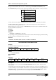
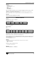
Attributes:
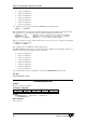
Controller Read Write Command Multi-
Axis
Scaled Default Range
NextMove PCI
0
0 ≤ x ≤ 7
MintDrive &
ServoNode 51
0
0 ≤ x ≤ 16
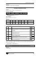
Description:
The
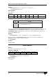
AUXENCODERMODE keyword accepts a bitmap as follows:
Bit
Purpose Description NM SN/
MD
0 Encoder
direction
Can be used to reverse the count direction of the auxiliary
encoder input channels, to overcome possible wiring problems.
0 – Normal
1 – Reversed
1 Encoder
type
Can be used to select the encoder type:
0 – Differential line receiver
1 – Single-ended encoder
2 Input
source
Selects the input source:
0 – Encoder inputs A and B
1 – Step (A) and Direction (B)
3 Virtual Creates a virtual auxiliary encoder reference. The
AUXENCODERSPEED keyword is used to set the reference.
4 Off
Turns off all auxiliary encoder processing to give an increase in
servo loop execution speed.
Example:
Check the count direction (polarity) of the auxiliary encoder using the Mint WorkBench QuickWatch
window. If the auxiliary encoder count decrements when the motor shaft is rotated clockwise, then the
count direction may be reversed:
AUXENCODERMODE = AUXENCODERMODE OR 1
Note: Changing AUXENCODERMODE can affect position related keywords
See Also:
AUXENCODER