
Installation guide


Mint™ v4 Advanced Programming Guide
20 MN1270 02.2002
Mode Action
3 Perform a controlled stop on the axis at the rate specified by the ERRORDECEL
parameter, leave the axis enabled. When the axis is idle the error handler will be
called.
4 The forthcoming software limit is anticipated. The forward or reverse software limit
becomes a temporary stop point and the motion will decelerate at the rate specified by
DECEL to stop on the software limit. The axis will remain enabled. When the axis is
idle the error handler will be called. (Software Limit only).
5 Call the error handler only.
6 Ramp the DAC to zero with a rate set with the DACRAMP parameter. The axis will be
disabled when the DAC reaches zero and the error handler will be called.
Each of the errors for each of the axes can be given a separate mode and the controller will react
accordingly.
As the above table details, the error handler will be called once the required action has been completed.
However this may not always be required and the
ERRORMASK parameter allows the user to specify
whether or not a specific error on an axis will call the error handler. By default all errors will call the
error handler on completion of the required action.
The keyword
ERRORMASK accepts a bit pattern where if the bit is set the error handler will be called
when that error condition becomes active. The bits are the same as for the axis error pattern listed
above.
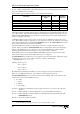
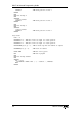
The table below shows the possible error modes for each of the different types of errors.
Mode
Error 0 1 2 3 4 5 6
Abort
Hardware Limit
Software Limit
Following Error
External Error
Analog Error
Slave/Sync Error
5
Velocity Error
Every 2ms all of the potential error sources are checked. If any of them are true the axis status is
immediately flagged and the appropriate action is initiated. Upon completion of the desired action, if
the error mask allows and one exists, the error handler will be called.
The Axis Status flag is a real time indication of the status of the axis, for example if an error input is
pressed, the axis status will reflect the state of the error input and when it is released the axis status will
reflect this even if the error produced by this event is still being handled.
The Axis Error flag is a latched bit pattern of errors that have been handled, the axis error flag will on
be set when the error occurs and will remain set until cleared by either canceling the errors using the
CANCEL keyword, or manually clearing a specific bit by writing to the axis error bit pattern using the
AXISERROR keyword
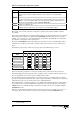
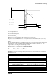
Below is an crude ‘timing’ diagram showing the change in state of the various flags in response to an
error input. The mode for the axis is set up as mode 3 (decelerate using the
ERRORDECEL rate).
5
Not user selectable