
Installation guide


Creating Motion
MN1270 02.2002 11
PRECISIONINCREMENT.0 = 10 : REM 10mm table steps
PRECISIONOFFSET.0 = 0 : REM Assume start of table is home
PRECISIONMODE.0 = _lsDUAL_TABLE : REM Turn on dual table compensation
3.5 Hold To Analog
This section applies only to the NextMove product range.
The purpose of the HTA is to keep the value on an analog input constant where the position of an axis
has an effect on that analog value. Once the controller is put in HTA mode, position is controlled in
order to keep the analog value constant.
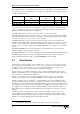
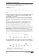
HTA effectively adds a force control loop around the outside of the standard servo loop. Figure 3
shows a block diagram of the force control system. The output of the force controller is a position
demand signal which is applied to NextMove’s standard position controller. The transfer function of
the position control loop is therefore G
c2
(s)=1.
Figure 3: Flow of Force Control System
In order to satisfy a majority of plant models, the force control loop implemented is as follows:
Velocity Error Gain Error Damping=×+ ×∆
where:
Velocity is the demand signal passed to the positional control loop.
Error is the difference between the desired analog value and the measured value.
∆
Error is the change in error from the current and previous sample.
Gain is the proportional gain term.
Damping is the damping term.
Within the force control loop, the analog input channel is sampled and filtered if required. The error
between the measured and the desired value is then calculated and checked against the error deadband.
If the error is not within the deadband then a velocity demand will be generated.
The velocity demand is then limited within the currently defined motion trapezoid. This means that the
axis acceleration or deceleration will be limited to the currently set values and the maximum velocity
will be limited to the currently set speed value.
3.5.1 HTA Setup
In order to perform HTA, an analog input channel has to be associated with an axis. The force control
loop must then be tuned and the analog filter and deadband used to control sensitivity. The motion
profile is defined to control the speed and acceleration of the axis as required.
The force control algorithm is essentially error driven. It will try to minimize any error between the
current analog input channel value and the user specified analog hold value