
Installation guide


Mint™ v4 Advanced Programming Guide
10 MN1270 02.2002
The size of the backlash is set with the BACKLASH keyword, the sign of the backlash is used to indicate
in which direction the backlash was taken up during the homing cycle.
Example:
BACKLASH[0,1] = 0.01, -0.2
This indicates that backlash on axes 0 and 1 is 0.01 and 0.2 user units respectively.
The rate at which compensation is applied is controlled with the
BACKLASHINTERVAL keyword. As the
axis changes direction, it will take the specified number of servo cycles to apply the compensation size.
3.4.2 Leadscrew Compensation
Inaccuracies in the manufacture of leadscrews result in discrepancies between the theoretical and actual
linear position of a nut. This error is called Lead Error. Leadscrew Compensation is a software
function that attempts to correct Lead Error.
Many leadscrew manufacturers can provide a lead precision table for each leadscrew supplied. This
table details the actual nut position for a number of theoretical positions along the usable length of the
leadscrew. The positions are usually measured from one marked end of the screw and are taken at
regular intervals. There may be a table for travel in both directions, effectively allowing for backlash as
well.
The controller stores similar tables for each axis. Each entry in a table will be the absolute actual
position of the nut in user units. The table is referred to as a
PRECISIONTABLE. It is possible to
specify a uni-directional or bi-directional tables.
The theoretical position increment between consecutive entries is programmable and applies to the
whole table. This is the
PRECISIONINCREMENT. The number of entries in a table will be
programmable limited only by memory space. The compensation feature can be turned on and off.
If Leadscrew Compensation is turned on the measured positions will be modified by the values stored in
the Precision Tables. A modified value will be linearly interpolated between two adjacent table entries.
The table entries used are based upon the theoretical measured position and the
PRECISIONINCREMENT. As the home position may not coincide with the start of the table, a position
offset must be added to the measured position prior to table lookup. This is the PRECISIONOFFSET.
Leadscrew Compensation will be turned off automatically if the position falls outside the range of the
Precision Table. It will be automatically turned back on when the position falls within the range of the
table.
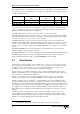
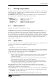
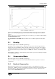
Leadscrew compensation assumes that the leadscrew can be described as:
where fwd x are the actual values for travel in direction from A to B and rev x are the actual values for
travel in the direction from B to A. For single table compensation, the fwd x values would apply in both
direction.
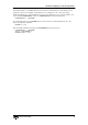
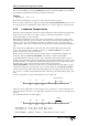
For a dual table leadscrew, the values might be
DIM fwdTable (5) = 10.02, 20.01, 30.00, 40.01, 50.01
DIM revTable (5) = 10.01, 20.02, 29.99, 40.00, 50.01
PRECISIONTABLE(0, fwdTable, revTable) : REM Forward and reverse tables
A
B
fwd 2fwd 1 fwd 3
rev 2 rev 3rev 1
Increment Size
A
B
20.0210.01 29.99
20.01 30.0010.02
10 mm