
Installation guide


Creating Motion
MN1270 02.2002 7
3.1 Gearing Compensation
All sampled master / slave systems have an inherent lag in the system. This lag is speed dependant, the
faster the master axis, the larger the lag seen. Gearing compensation can be used to overcome this lag
for the
FOLLOW, FLY and CAM move types.
The
GEARING keyword allows the lag or lead position of the slave axis to be controlled or removed.
The compensation is accomplished by feeding forward the slave velocity.
Example:
MASTERSOURCE.0 = 0 : REM Master is axis position
MASTERCHANNEL.0 = 3 : REM Master is axis 3
GEARING.0 = 100.0 : REM Compensate lag
GEARINGMODE.0 = 1 : REM Turn on gearing compensation
FOLLOW.0 = 1.0 : REM Start following the master
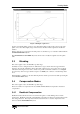
3.2 Spline and P.V.T.
Splines are only available on the NextMove product range.
A SPLINE move provides a means of specifying motion where arbitrary position and velocity
information needs to be specified in terms of time. The resulting motion is then calculated such that the
motion profile is continuous in position and velocity (acceleration and jerk also if no velocity data is
given). The Spline motion is defined using a number of segments. Each segment defines the how far
the slave axis will travel in a specified time. The Spline segments are placed in a table for a background
execution. Once these segments have been defined, NextMove will interpolate between them and ‘fill
in’ the missing information, producing a smooth path as it goes. Splines can be performed on any
number of servo or stepper axes.
3.2.1 Spline Tables
A spline cycle is broken up into a series of segments which make up the profile. A spline table is set-up
in an array of any name where the normal Mint syntax applies to the array.
For example:
DIM myPos(11) = 10,1,2,3,2,1,2,3,1,2,3
where the first element determines the number of points in the spline profile and each subsequent value
defines a spline segment. A segment can be defined in either relative or absolute positions . The type
of spline performed is determined by value passed to the
SPLINE keyword.
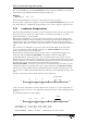
There are three types of profile available:
1. Spline 1. Only position data is used and a smooth path (in position, velocity, acceleration and
jerk) is produced. The axis may not pass through the points specified in the spline table,
depending on the values.
2. Spline 2. Only position data is used and a smooth path (in position and velocity) is produced.
The axis will pass through the points specified in the spline table.
3. PVT. Position and velocity information is used to produce a smooth path (in position and
velocity). The velocity information for each segment is defined in array. At the segment, the
axis will pass through the points specified at the velocity specified.
Before the spline can be executed, a segment duration must be defined. This is done with the
SPLINETIME keyword which specifies a duration in milliseconds. Alternatively, individual segment
durations can be specified by the use of a duration array.
The
SPLINETABLE keyword is used tell NextMove which arrays to use for the spline. SPLINETABLE is
a function style keyword. For example, to use the position array myPos and the duration array myDur:
SPLINETABLE ( 2, myPos, NULL, myDur )
where 2 is the axis number. The NULL parameter indicates that there is no velocity data.