
Installation guide


Keyword Reference Guide
MN1270 02.2002 119
Controllers Supported:
NextMove PCI NextMove PC NextMove BX MintDrive ServoNode 51
Format:
PWMONTIME[axes] = <expression> {,<expression> ...}
v = PWMONTIME[axis]
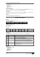
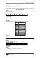
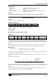
Controller Read Write Command Multi-
Axis
Scaled Default Range
NextMove
1000
-16000 to 16000
Description:
The four stepper axes can be configured as PWM or stepper outputs. Configuring one axis as PWM
will change all axes currently configured as stepper into PWM. Once in PWM mode, the frequency and
duty cycle of the pulse train can be controlled.
The
PWMONTIME keyword controls the duty cycle or mark space ratio of the pulse train. It specifies the
amount of time that the output is on (active) in 125 ns ticks. A negative value sets the stepper axis
direction pin low.
Example:
PWMPERIOD = 4000
PWMONTIME = 1500
This would give a pulse train where the pulse output was active for 187.5 µs and inactive for 312.5µs.
PWM is not available on a stepper NextMove daughter board.
See also:
BOOST, CONFIG, FREQ, PULSE, PWMPERIOD, STEPDIRECTION
PWMPERIOD/PWP
Purpose:
To control the period of a PWM output train.
Controllers Supported:
NextMove PCI NextMove PC NextMove BX MintDrive ServoNode 51
Format:
PWMPERIOD = <expression>
v = PWMPERIOD
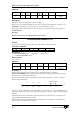
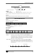
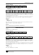
Controller Read Write Command Multi-
Axis
Scaled Default Range
NextMove
2000
-1000 to 16000
Description:
The four stepper axes can be configured as PWM or stepper outputs. Configuring one axis as PWM
will change all axes currently configured as stepper into PWM. Once in PWM mode, the frequency and
duty cycle of the pulse train can be controlled.
The period is defined as the number of 125 ns ticks. The four PWM outputs must share the same PWM
period. This will default to 250 microseconds (4KHz). The PWM period can be set or read back with
the following functions:
Example:
PWMPERIOD = 8000
This would set a PWM period to 1ms (1KHz).