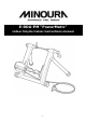
E-RDA-PM “PowerMatic” indoor bicycle trainer instructions manual -1-
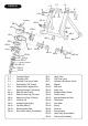
F-2 F-4 SCHEMATIC F-4 F-8 R8-1 F-9 F-1 F-7 SR-13 Screw-M SR-12 ER-3 ER-1 SR-12 ER-10 M8-3 ER-7 M8-4 M8-4 ER-8 ER-23 SR-5 Screw-L ER-12 SR-14 ER-24 SR-8 ER-14 ER-13 ER-16 ER-17 Screw w/ washer ER-18 ER-19 ER-20 F-1 : F-2 : F-4 : F-7 : F-8 : F-9 : R8-1 : M8-3 : M8-4 : SR-5 : SR-8 : SR-12 : SR-13 : SR-14 : Coupling (Right) Coupling (Left) Coupling Cover (move side) Hub Handle (3/8” thread) Wheel Position Adjust Knob Hub Nut Protector (Grommet) RDA-850 Main Frame Rubber Frame Cap (38.
IMPORTANT NOTES • • • • • • Read all instructions carefully before use. Some assembly required. Keep the manual handy at all times. Do NOT use trainer for any other purpose than instructed. The trainer is manufactured to precise standards. Disassembly may void your warranty. "Magturbo" and “RDA” are the trademarks of Minoura Co.,Ltd. and may not be copied. WARNINGS ! ! Use two-wheeled bicycles only. Tandems may be used if balanced correctly.
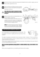
HOW TO SETUP YOUR E-RDA-PM TRAINER 1 Open the frame support legs and fit the rubber feet at the correct angle so the base is in full contact with the floor. NOTE: If the both legs don’t touch the floor at same time and if one side of the leg is still slightly raised, pull up the leg upward strongly then place the trainer on the floor again.
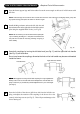
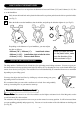
Hold the bike firmly by hand and turn the right side hub handle clockwise until the coupling comes into contact with the right side skewer nut. 6 Adjust each height of the Mag unit and the assistant roller to fit to your rear wheel perfectly and tighten the bolts firmly. (see Fig. G) ! 7 (Fig. G) Each rubber roller is made to contact the rim ONLY. Contact with the tire may cause the tire to burst during use. Adjust the wheel position by checking the double-circle position indicators on both sides.
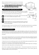
HOW TO INSTALL THE REMOTE LEVER You can install the remote lever on anywhere the diameter is between 22.2mm (7/8”) and 31.8mm (1-1/4”) like as on the handlebar. 1 Fully loosen the knob bolt on the plastic holder until it stops then push down the bolt to open the holder. (see Fig. J) 2 Place the holder onto the handlebar, shut the holder, and pull up the bolt then tighten it. (see Fig. K) Shim (Fig. J) (Fig. K) Depending on the diameter of your handlebar, you must adjust the shim as follows; • 22.
When it reaches the maximum level you have set, the resistance will be limited at this level, except constant increase to your speed. ! To make any adjustment to the unit, make sure you are off the bike, and that the trainer has come to a complete stop and that nothing is still moving. TROUBLE SHOOTING YOUR REMOTE SHIFTER UNIT If you cannot shift to either the lowest (L) or the highest (H) position, it is possible that the inner wire of the remote shifter cable is too long and the wire tension is loose.
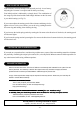
HOW TO USE THE GOVERNOR Your resistance unit has already been adjusted precisely in our factory. Adjusting the Governor is an option and not always necessary. Your initial position is indicated by a triangle decal. The combination of the orange tip of the decal and the small triangle indicator on the Governor is your initial setting (see Fig. P).