Home Theater Series NANOAVR DL 8-CHANNEL HDMI AUDIO PROCESSOR WITH DIRAC LIVE® TECHNOLOGY User Manual mi niDSP Ltd, Hong Kong / www.minidsp.
Revision history Revision 1.0 1.1 1.2 Description Initial public release Custom configuration, AVR configuration, smartphone app, channel mode Updated firmware update procedure Date 4 December 2014 19 May 2015 20 May 2015 mi niDSP Ltd, Hong Kong / www.minidsp.
T ABLE OF C ONTENTS Important Information....................................................................................................................................5 System Requirements..................................................................................................................................5 Disclaimer/Warning ....................................................................................................................................5 Warranty Terms...................
3.5.3 Completing the measurements................................................................................................ 27 3.5.4 Viewing and redoing measurements ........................................................................................ 27 3.6 Saving and loading projects ............................................................................................................ 27 4 Filter Design ........................................................................................
I MPORTANT I NFORMATION Please read the following information before use. In case of any questions, please contact miniDSP via the support portal at minidsp.desk.com.
Warning: This equipment has been tested and found to comply with the limits for a Class B digital device, pursuant to Part 15 of the FCC Rules. These limits are designed to provide reasonable protection. This equipment generates, uses and can radiate radio frequency energy and, if not installed and used in accordance with the instructions, may cause interference to radio communications. However, there is no guarantee that interference will not occur in a particular installation.
1 P RODUCT O VERVIEW Thank you for purchasing a nanoAVR DL HDMI audio processor powered by Dirac Live®, the world’s premier room correction solution. We are delighted to offer you this software and hardware combination, the fruit of extensive research and development and years of experience in sound system tuning. The nanoAVR DL is a digital audio signal processor (DSP) running the Dirac Live® room correction algorithm.
Computer connectivity is used to perform acoustic measurements and generate digital room correction filters for Dirac Live®. Up to four sets of correction filters can be stored on the NanoAVR DL processor and recalled from the front panel, via an infrared remote, or with the miniDSP smartphone app. Once the processor is fully configured, the computer is no longer needed. 1.
Illustration of Dirac Live® impulse response correction Dirac Live® accomplishes this using mixed-phase filters – filters that match a desired magnitude response and generate a customized impulse response. This contrasts with the minimum-phase and linear-phase filters that are commonly used in audio applications.
1.3 C ONFIGURATION OVERVIEW The steps for configuring the nanoAVR DL HDMI audio processor with Dirac Live® to optimize your home theater system is summarized as follows: 1. Connect the nanoAVR DL audio processor into your system and install software. See Section 2, Installation and Setup. 2. Execute a series of acoustic measurements on your computer using the Dirac Live Calibration Tool For miniDSP program, to capture the acoustic behavior of your speakers and room. See Section 3, Acoustic Measurement.
2 I NSTALLATION AND S ETUP 2.1 S OFTWARE INSTALLATION AND LICENSE ACTIVATION Please read this section carefully prior to installing the software. 2.1.1 Framework installation Prior to installing the software, download and install the following frameworks. You will need to accept the license agreements in order to successfully complete the installation. If you haven’t updated these recently, check that you have the latest versions prior to running the miniDSP install programs. Microsoft .
2.1.3 License activation 1. 2. If you are running the Dirac Live Calibration Tool already, quit from that program. (You cannot run this program and the NanoAVR DL Utility program at the same time.) Start the NanoAVR DL Utility program. It will appear as shown on the left below. 3. Connect your nanoAVR DL processor to your computer via USB, then click on the Connect button. It will change to a green tick. 4. Click on Get Activation Serial Number.
Notes: 1. The serial number that must be entered in the activation screen is not the serial number printed on the hardware unit. A unique serial number specific to Dirac Live is programmed into the firmware of each unit and can only be accessed with the nanoAVR DL Utility program (step 4 above). 2. The email address used during license activation is not related to your user account on miniDSP.com.
2.2 H ARDWARE CONNECTIVITY All connections to the nanoAVR DL are made on the rear panel. 2.2.1 HDMI input and output Two HDMI connections are available for input, and one for output. The input connectors can be connected to any HDMI source such as a Blu-ray or DVD player, provided that the source is capable of producing a linear PCM audio signal. Other sources may include media streaming devices and computers with an HDMI port †.
2.2.3 DC Power The supplied 5 VDC power supply includes a set of interchangeable power pins. Fit the correct pins for your country. Connect the DC plug to the 5 VDC power socket. HDMI units communicate with a set of “hand-shaking” signals in order to establish the capabilities of each device. We recommend that for at least the first time the system is powered up, equipment be powered on in this order: TV, AVR, nanoAVR DL, source/player. 2.2.
3 A COUSTIC MEASUREMENT The Dirac Live Calibration Tool For miniDSP uses a set of measurements made in your listening room to gather all the acoustical information about your room and speakers that it needs to calculate the correction filters. The measurements are made using the nanoAVR DL HDMI audio processor and a miniDSP UMIK-1 measurement microphone (must be purchased separately). 3.
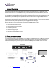
3.2 C ONNECTIONS FOR ACOUSTIC MEASUREMENT The figure below shows a typical connection diagram for performing acoustic measurement. No changes to the existing audio connections are needed. Simply: 1. Connect the supplied USB cable (type A to type B) from the nanoAVR DL to a USB port on the computer. 2. Connect a USB cable (type A to mini type B) from the UMIK-1 to a USB port on the computer.
3.3 A/V RECEIVER CONFIGURATION The AVR connected to the nanoAVR DL output needs to be set appropriately for best results from Dirac Live. This must be done prior to performing the Dirac Live calibration. 3.3.1 Speaker distance (delay) Set the speaker distance (or equivalently, delays) in your AVR using the procedure recommended by your AVR manufacturer.
3.4 C ONFIGURING FOR MEASUREMENT Start Dirac Live Calibration Tool For miniDSP. Be sure to quit the NanoAVR DL Utility program before starting Dirac Live Calibration Tool. Running the two programs at the same time will result in communication conflicts and odd behavior. Logo and status/progress bar This area shows a progress bar with current status when the program is performing calculations. If the program seems unresponsive at any time, check the status here.
3.4.1 Sound System tab On the Sound System tab, set the following parameters. Choose system configuration Use the dropdown menu to select the system configuration. For home theater use, usually 5.1 Speaker System or 7.1 Speaker System will be selected. However, you should choose Custom System for a different number of channels, a different channel assignment, or to disable LFE gain alignment (see Custom System configuration below for more information).
3.4.2 Mic Config tab On the Mic Config tab, set the following parameters. Recording device Preset to the UMIK-1. If UMIK-1 is not showing, ensure that the UMIK-1 is connected securely to the computer via USB, then go back to the Sound System tab and click on Rescan. Then use the drop-down menu to select the “Microphone” item underneath “UMIK-1”.) Recording channel Select 1 from the drop-down menu. Microphone calibration file Each UMIK-1 measurement microphone is individually calibrated to ensure accuracy.
3.4.3 Output & Levels tab The Output & Levels tab is used to set the signal levels used in the subsequent measurement: 1. 2. Set Output volume quite low. If you have another volume control “down-stream” of the nanoAVR DL, set it about halfway (or around -20 dB) and increase it later if needed. Connect an HDMI source to the currently selected HDMI input. (This is needed so that audio can be transmitted over the HDMI output.) 3.
3.4.4 Custom System configuration On the Sound System tab, choose the Custom System configuration if any of the following apply: Your system does not fit any of the three predefined configurations (Stereo, 5.1, 7.1). You want to use a different channel mapping than the default. You do not want the nanoAVR DL to calibrate for a 10 dB LFE alignment gain on the subwoofer channel. (LFE alignment gain is used to compensate for the reduced level of the LFE track as it is recorded to movie soundtracks.
3.5 R UNNING THE MEASUREMENTS Acoustic measurements are performed on the Measurements tab. Measurements should be performed under good conditions. While the measurement technique used by Dirac Live is quite robust, low-frequency noise (traffic, machinery, aircraft, storms) in particular can adversely affect measurement accuracy. A high level of ambient noise can also prevent the algorithm from analyzing the test sweep signal properly.
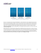
3.5.1 Listening environment The Measurements tab presents three different listening environments as a visual guide to positioning the microphone for each of the nine measurements: Chair, for a single listening seat; Sofa, for multiple listening seats; and Auditorium, for a dedicated home theater or larger venue with staggered seating. Use the icons at the left of the screen to select the listening environment.
For example, if using the Chair listening environment, spread the microphone positions over a circle with a diameter of a meter (three feet). Vary the height of the microphone up and down by 30 cm (one foot) from the initial position. If using the Sofa or Auditorium listening environment, again spread the measurement locations over the full listening area and vary microphone height by a significant amount.
3.5.3 Completing the measurements After each successful measurement, the location marker (red arrow) will advance to the n ext location. Move the microphone to that location, using the three views (top, front, oblique) as a guide to positioning it. Then click on Start again. Repeat this process until all nine locations have been successfully measured. Note: it is good practice to save the project periodically while performing measurements (see Saving and loading projects below). 3.5.
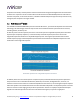
4 F ILTER D ESIGN T he Filter Design tab shows sets of graphs for the various channels. Click on the tabs at the right to display the response graphs for different sets of channels (left and right, center, subwoofer, and surrounds, in the case of 5.1 and 7.1 systems). For each set of graphs, a number of variants can individually be turned on and off with the checkboxes above the graphs. Avg. spectrum (before) The average of the measured magnitude responses. These plots are shown in light blue. Avg.
The graphs showing all nine measurements are useful for seeing how much variation there is across the listening area: To display the impulse response instead of the magnitude response, click on the Impulse button at the top left of the display. All nine individual impulse responses can be shown as well as the average response. The predicted impulse responses after correction can be viewed after filters are generated with the Optimize button (see Generating correction filters below).
To unlink a channel, click on its chain icon. It will then be unlinked from the other channels. To link it to another channel or groups of channels, drag its tab on top of the channel or group of channels that you want it linked to. Initially, you may wish to link all speaker channels together, as shown at right in the diagram above, as this will make it easier to experiment with target curves.
4.3 D ESIGNING YOUR TARGET CURVE The target curve is the desired in-room frequency response with the nanoAVR DL processor performing digital room correction. 4.3.1 The Auto Target When first viewing the Filter Design tab, an estimated target curve suitable for your speakers is shown as the red curve. This calculated target curve can be restored at any time by clicking on the Auto Target button. Note: restoring the auto target will erase the current target curve.
you may be happy with the in-room response at higher frequencies, so you can set the frequency region to limit correction to the modal region (up to 300 Hz, in a typical room). To alter the region of correction, drag the grey handles on either side of the graph. Note that you can’t drag these handles over an anchor point, so you may need to move or delete an anchor point that is “in the way.” 4.3.
High-frequency “tilt” The target curve is the desired measured response of loudspeakers in a room, In contrast to measurements made of a loudspeaker during its design under anechoic (measured in free space) conditions.
4.4 G ENERATING CORRECTION FILTERS Once you have a target curve set to your satisfaction, click on the Optimize button. The status bar will update as the algorithm progresses. The entire algorithm may take some time to complete, depending on the speed of your computer. When the algorithm completes, the predicted average magnitude response will be shown in green. (The predicted impulse response can be viewed by clicking on the Impulse button.
4.5 D OWNLOADING AND MANAGING FILTER SETS The Export tab initially shows four empty “slots” for filter sets (a filter set is one filter for every channel). Filter sets are managed with a “drag and drop” metaphor: To load the most recently generated filter set into the processor, drag the box at the top left (labeled “HT 15 Aug 2105” in the example) and drop it onto an empty slot.
5 USING THE NANOAVR DL PROCESSOR Once the desired correction filters have been downloaded into the nanoAVR DL processor, the computer is not required and can be disconnected. The front panel, an infrared remote, or the miniDSP smartphone app can be used to control: Filter set selection HDMI input selection Master volume (remote control and smartphone app only) Master mute (remote control and smartphone app only) Dirac Live® filtering on/off (remote control and smartphone app only) 5.
5.3 I NFRARED REMOTE CONTROL Many standard and programmable remote control units can be used with the nanoAVR DL processor. Instead of adding another remote to your collection, the processor can “learn” the control codes of your current infrared (IR) remote if it supports one of the following remote control codes: NEC Sony Philips RC6 Apple Remote Learning is done with the nanoAVR DL Utility program. After starting the program, click on the Connect button.
5.4 S MARTPHONE CONTROL APP The nanoAVR DL can be controlled with the miniDSP control app for Android and iOS (Apple) smartphones and tablets. To control the nanoAVR DL over the network, connect an Ethernet cable from the nanoAVR DL’s Ethernet port to a free port on your Ethernet router or switch. The diagram below illustrates a typical case . The network must be capable of DHCP so that the nanoAVR DL will be given an IP (network) address.
6 A DDITIONAL I NFORMATION 6.1 T HE NANOAVR DL UTILITY PROGRAM The NanoAVR DL Utility program is an auxiliary program for configuring certain functions of the nanoAVR DL. It is not used for measurement or calibration. Master volume Displays the current master volume setting. Mute Mutes all audio output. Connect/Connected Click on the Connect icon to connect to the nanoAVR DL. To disconnect, quit from the utility program. Source Displays the currently selected HDMI input.
Be sure to quit Dirac Live Calibration Tool For miniDSP before starting the NanoAVR DL Utility program. Running both programs at the same time may result in communication conflicts and odd behavior. 6.2 C HANNEL MODE The HDMI protocol includes information specifying the number of audio channels in the HDMI stream.
6.3 S PECIFICATIONS Computer connectivity Driverless USB 2.0 configuration and control interface for Windows and Mac OS X Ethernet control (RJ45 / 100Mbps) with ZeroConf support (autoIP/DHCP) HDMI inputs 2 x HDMI 1.4a selectable from software, front panel or IR remote Input sample rate: 32 - 192 kHz HDMI Outputs 1 x HDMI 1.
6.4 T ROUBLESHOOTING The following table lists the most common causes of issues with the nanoAVR DL. If following this table does not provide a solution, see Obtaining Support below. Item# Symptoms Troubleshooting recommendation 1 Cannot install software a. Confirm that you downloaded and installed the required frameworks first (see Software Installation). 2 The Dirac activation screen does not recognize the serial number a. Do not use the serial number printed on the label of the unit.
Levels, set the gain to 100. 8 9 10 Unable to generate correction filters (Optimize button) No audio or video while playing Video but no audio c. Increase system output volume. a. Check that your computer is connected to the Internet and able to pass HTTP (web) traffic. b. Check that you do not have any other program running that is attempting to communicate with the nanoAVR DL, such as the nanoAVR DL utility program. a. b. Check that all HDMI cables are securely seated.
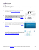
6.5 MCU FIRMWARE UPDATE miniDSP may periodically provide an update to the nanoAVR DL MCU firmware to enable new features. To update the MCU firmware: 1. Download and install the latest nanoAVR DL Utility package from the User Downloads section of the miniDSP website. 2. Connect the nanoAVR DL to your computer via USB. 3. Start the nanoAVR DL Utility program. 4. Click on the Connect button. The button will display a green tick if connection is successful. 5. Click on the Upgrade Firmware button.
7. Click on the Connect button. The status display should change to show that the program has connected: 8. Click the Load Hex File button. Browse to the .hex firmware file located in the unzipped download folder and select it. This file will have a name like nanoAVR_DL_v1_23.hex. The status will show that the hex file has loaded successfully: mi niDSP Ltd, Hong Kong / www.minidsp.
9. Click the Erase-Program-Verify button. The progress bar will update. After some time, the status will update to show successful completion. DO NOT DISCONNECT THE USB CABLE OR POWER FROM THE NANOAVR DL WHILE THIS IS IN PROGRESS. DOING SO MAY “BRICK” YOUR NANOAVR DL. 10. Click the Run Application button to reboot the nanoAVR DL. 11. Click the Disconnect button 12. Close the PIC32 Bootloader application window. 6.6 O BTAINING SUPPORT 1. Check the forums on miniDSP.