
User manual


miniDSP Ltd, Hong Kong / www.minidsp.com / Features and speci fications subject to change wi thout pri or noti ce 39
6.2 CHOOSING GAIN STRUCTURE SETTINGS
The input sensitivity is the voltage that generates a full-scale digital input signal to the DDRC-88A’s DSP (digital
signal processor). The output gain setting specifies the voltage that results from a full-scale digital output signal
from the DSP.
The best choice of input sensitivity and output gain settings can be determined in two ways: by the output level
of the source and the input sensitivity of the amplifier, or by the resulting input-output gain of the DDRC-88A.
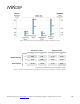
We suggest initially using Figure 6.2 as follows:
1. Knowing the maximum output level of your source equipment, run a line across to either Unbalanced input
or Balanced input. The best input sensitivity is the one that your line intersects. If you are in the red zone,
limit the master volume control on your source equipment to avoid overloading the DDRC-88A input.
2. Compare the maximum output level of your source equipment with the input sensitivity of your
amplification, and choose the lowest number. Then run a line across to either Unbalanced output or
Balanced output. The best output gain setting is the one that your line intersects. (With this
recommendation we allow the possibility that the DDRC-88A may overdrive the amplifier. Since Dirac Live
will tend to reduce output levels somewhat, over-driving it is unlikely in practice.)
If your equipment offers a choice of unbalanced or balanced inputs or outputs, this diagram can also be used to
help choose which type of connection to use. Note that there is no sensitivity adjustment for balanced inputs
(the only available choice is 8 VRMS). In addition, if an input channel is set for 0.9V sensitivity, a balanced
connection can not be made to that channel.
All input channels must have the same type of connection (balanced or unbalanced) and the same
input sensitivity setting. (Output channels can have a mix of balanced and unbalanced connections
and a mix of output gain settings. If using a mix, always do a Gain structure optimization.)
Changing connection type or gain structure settings of individual channels will invalidate all of your
existing Dirac Live projects. Therefore, if making a change to gain structure, you must either change
all channels in the exact same way, or completely redo your Dirac Live calibration afterwards.
If, after performing an initial calibration with Dirac Live Calibration Tool for miniDSP, you find that the input-
output gain is not suitable for your system, then refer to Figure 6.3 to choose different settings that match your
desired input-output gain.