miniDSP 4x10 Hd USER MANUAL Revision Description Date V1.0 Initial revision 28-06-2012 V1.1 Updated section on volume control 03-08-2012 www.minidsp.com miniDSP Ltd – Hong Kong / Email : info@minidsp.
Contents 1 2 Product Introduction .............................................................................................................................................................................................. 3 System Connectivity ............................................................................................................................................................................................... 5 2.1 Board connectivity ...............................................
1 Product Introduction miniDSP 4x10 is a Digital Audio Signal Processor (DSP) capable of performing a wide range of applications, from filtering, equalization to time alignment. Typically located between an audio source (CD player/Receiver/Preamp/PC .. etc) and the amplifier, a miniDSP will provide unparalleled tuning flexibility to improve your audio system’s performance.
DISCLAIMER / WARNING An incorrect miniDSP configuration could easily damage your audio system. MiniDSP can not be responsible for any damage that may result from the improper use of this product. As with any other product, we do recommend that you carefully read the manual and other technical notes to insure you fully understand how to operate the board.
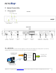
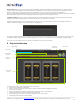
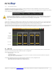
2 System Connectivity 2.1 Board connectivity Front View Display Active Digital source Active Preset Master volume & Source /Preset selection IR Receiver Rear View 2x Un-balanced 12VDC RCA inputs Power Input 2.2 2 x Balanced Inputs 8 x Un-Balanced Outputs 8 x Balanced Outputs Toslink/SPDIF/ AES-EBU Inputs Toslink + SPDIF + AES-EBU outputs USB Control Typical setup INPUTS Analog/Digital Audio source (e.g.
2.2.1 DC Power connectivity miniDSP 4x10 Hd is provided with a universal 12V DC power supply with IEC power connector. If the IEC cable provided isn’t the same as your country’s plug, you can easily source/re-use such cable from computer supplies. Note that we recommend you to plug the Power Supply to the miniDSP enclosure before connecting it to the AC power. 2.2.2 Audio connectivity miniDSP can accept both balanced and un-balanced audio inputs/outputs.
Output gain control: A blue DIP switch control on the output section allows user to control the output gain both the unbalanced and balanced outputs on a “per channel” basis. UP position 8Vrms (balanced) 2Vrms (Unbalanced) DOWN position (Default) 4Vrms (balanced) 0.9Vrms (Unbalanced) Channel number 2.
3 Software Setup miniDSP platforms are controlled and configured over a USB connection. Our software, so called plug-in, must be purchased from our online webstore separately. The following section will highlight the steps required to configure the miniDSP plug-in. In order to familiarize yourself with the software first, do not connect any amplifiers to your miniDSP outputs until you understand each object. Get to know the software first, then start playing audio… 1.
a) Synchronize: With this option, the current plug-in configuration will be loaded/flashed to the MiniDSP and your plug-in turned to “On-line” mode. Warning that it will overwrite whatever configuration was previously loaded on the board. If you’d like to load a different configuration, click cancel and go to the settings tab to load one of your previously saved configurations. If you previously installed a different firmware version on your kit, this button will display: Synchronize & Upgrade.
4.1.2 Preset Memory selection The miniDSP 4x10 Hd allows the user to create up to 4 preset memories for a quick reconfiguration of the processor. Under each configuration, all settings of the platform are saved. Placed at the top of the user interface, the use of configurations couldn’t be easier. Simply toggle between configurations by clicking on the config button. The currently selected configuration WARNING: By toggling configurations, you may go from a working configuration (i.e.
Crosspoint buttons (ON) Analog inputs in Rows Digital inputs in Rows Note how labels of input channels and output channels followed on the Matrix mixer to simplify your routing. Let’s illustrate the concept of configuration of this block using a 3way configuration + 2 subs where both Left & Right signals are being mixed (combined). Mixing happens when multiple crosspoints are enabled within a column 4.
4.3.3 Output volume A fader control for +12 to -70dB digital gain control. Similar to the input volume control. 4.3.4 Crossover Controls for the Low& High pass filters are available when clicking on the Xover (crossover) button: The log scale graph gives you the equivalent response of the applied filter. By pointing the mouse anywhere on the plotted curve, the dB attenuation and respective frequency are displayed.
4.3.5 Parametric Equalizer • • • • • EQ band selection: Select one of the 6 x Parametric Equalizers Filter type: Select between Peak, Low Shelf, High Shelf Bypass: Disables the equalization but doesn’t reset the settings. A handy tool to check the influence of equalization on your system without resetting to zero. Note that the bypass button is per-band Bypass (not overall). Linking feature: Similar to the crossover dialog box, you can link up two EQ settings together.
4.3.6 Compressor /Limiter Typical Comp/Limiter settings Comp/ Limiter metering shows real time amount of attenuation by comp/limiter Comp/ Limiter chart Bypass Comp/ Limiter A compressor/Limiter allows dynamic range compression of the signal to prevent damage of your speakers. Extensive information is available online on the use of compressor/limiter. Please take the time to familiarize yourself with such processing block before using it. 4.3.
A warning may be shown during synchronization if you have the incorrect firmware loaded on your platform. Once the new plug-in installed, please browse to \\Program Files\MiniDSP\MiniDSP-8x8\firmware_tools\Windows. Three files can be found there: - Upgrade steps - Upgrade Tool excecutable - Firmware file The firmware upgrade summarizes to few simple steps: 1. Unplug the DC power 2. Press and hold the reset button while pluging the power to the board 3. Release the reset button 4. Connect the USB to the 5.
5 Troubleshooting The following symptoms were found to be the most likely cause of issues. Item# 1 Symptoms No audio on outputs 2 No audio on RMS input meters 3 Audio on input RMS meters but no audio on outputs Cannot reload configuration Cannot connect to the board 4 5 6 Cannot install software 7 Software running in background but not showing Problem unsolved by above suggestions 10 Troubleshooting recommendation - Make sure that audio signal is shown on the RMS input meters.