UTP VDS REMOTE LONG RANGE UNIT QUICK INSTALLATION GUIDE BROADCASTER REMOTE UNIT UTP VGA SPLITTER w w w . m i n i c o m . c o m International HQ North American HQ European HQ Jerusalem, Israel Linden, NJ, USA Dübendorf, Switzerland Tel: + 972 2 535 9666 minicom@minicom.com Tel: + 1 908 486 2100 info.usa@minicom.com Tel: + 41 44 823 8000 info.europe@minicom.com Technical support - support@minicom.
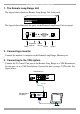
UTP VDS REMOTE LONG RANGE UNIT 1. The Remote Long Range Unit The figure below illustrates Remote Long Range Unit front panel. BROADCASTER REMOTE UNIT UTP VGA SPLITTER The figure below illustrates the ports on the Remote Long Range Unit rear panel. ON OFF 6VDC Power BR MONITOR PICTURE Brightness Picture adjuster adjuster TO CENTRAL UNIT Screen System 2. Connecting a monitor Connect the monitor’s connector to the Remote Long Range, Monitor port. 3.
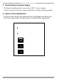
QUICK INSTALLATION GUIDE 4. Connecting to the power supply The Remote Long Range unit comes with a 6 VDC, 2A power adapter. Connect each unit to the power supply with the Power adapter and cord provided. 5. How to set the dipswitches The figure below illustrates the underside panel of the Remote Long Range unit, with 3 sets of dipswitches. The dipswitches are used for RGB compensation.
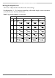
UTP VDS REMOTE LONG RANGE UNIT Setting the dipswitches All 3 sets of dipswitches must have the same settings. Set dipswitches 1 – 3 of each set according to the cable length, screen resolution and refresh rates. See the table below. Note! Dipswitch number 4 is not used.