Smart 108/116 IP User Guide 1111 W. 35th Street, Chicago, IL 60609 USA www.tripplite.com/support Copyright ©2012 Tripp Lite. All rights reserved.
Legal Notice Legal Notice This manual and the software described in it are furnished under license, and may be used or copied only in accordance with the terms of such license. The content of this manual is provided for informational use only, and is subject to change without notice. It should not in and of itself be construed as a commitment by Minicom Advanced Systems Limited, which assumes no responsibility of liability for any errors or inaccuracies that may appear in this book.
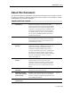
About this Document About this Document This document provides installation and operation instructions for the Smart 108/116 IP system, produced by Minicom Advanced Systems Limited. It is intended for system administrators and network managers. Chapters and Their Contents 1 Introduction Provides an introduction to the document, Smart Pg.
About this Document 8 Video Resolution and Lists video resolutions and refresh rates. Pg. 81 Lists recorded SNMP events. Pg. 84 Refresh Rates 9 SNMP Events Table Style Conventions Convention Used for Verdana Regular text. Arial Bold Names of menus, commands, buttons, and other elements of the user interface. Arial Italics Special terms, the first time they appear. Monospace Text entered by the user. Notes, which offer an additional explanation or a hint on how to overcome a common problem.
Table of Contents Table of Contents LEGAL NOTICE ........................................................................................... II ABOUT THIS DOCUMENT ...........................................................................III TABLE OF CONTENTS .................................................................................. V TABLE OF FIGURES ....................................................................................IX 1 INTRODUCTION .............................................
Table of Contents 3.2 LOGGING ONTO THE WEB CONFIGURATION INTERFACE ...................................24 3.2.1 Web Configuration Interface Tabs ...........................................26 3.2.2 Web Configuration Toolbar Buttons .........................................27 3.3 CONFIGURING THE NETWORK SETTINGS .....................................................27 3.3.1 Configuring Device ID Settings ...............................................27 3.3.2 Configuring the Device IP Address...............
Table of Contents 4.8.3 Editing a Key Sequence .........................................................51 4.8.4 Deleting Key Sequence(s) ......................................................52 4.9 SYNCHRONIZING MOUSE POINTERS ..........................................................52 4.9.1 Manually Synchronizing the Mouse ..........................................53 The USB Option.............................................................................................................
Table of Contents 6.3.1 Downloading Update Software and Latest Firmware ..................72 6.3.2 Update Software System Requirements ...................................73 6.3.3 Connecting the Smart 108/116 IP System................................73 6.3.4 Connecting the RS232 Download Cable....................................73 6.3.5 Installing the Software ..........................................................74 6.3.6 Starting and Configuring the Update Software ..........................74 6.3.
Table of Figures Table of Figures Figure Figure Figure Figure Figure Figure Figure Figure Figure Figure Figure Figure Figure Figure Figure Figure Figure Figure Figure Figure Figure Figure Figure Figure Figure Figure Figure Figure Figure Figure Figure Figure Figure Figure Figure Figure Figure Figure Figure Figure 1 – Smart 108/116 IP Unit Front Panel .......................................................... 14 2 – Smart 116 IP Unit Rear Panel................................................................
Table of Figures Figure Figure Figure Figure Figure Figure Figure Figure Figure Figure Figure Figure Figure Figure Figure Figure Figure Figure Figure Figure Figure Figure Figure Figure Figure 41 42 43 44 45 46 47 48 49 50 51 52 53 54 55 56 57 58 59 60 61 62 63 64 65 – – – – – – – – – – – – – – – – – – – – – – – – – Delete Key(s) Confirmation Box............................................................. 52 Relative Mouse Settings .......................................................................
Introduction Product Overview 1 Introduction Congratulations on adding Smart 108/116 IP to your remote access tools. This document provides installation and operation instructions for Minicom’s Smart 108/116 IP. It is intended for system administrators and network managers, and assumes that readers have a general understanding of networks, hardware, and software. Chapter 3 and Chapter 4 of this guide describe how to configure and operate the Smart 108/116 IP system remotely over IP.
Introduction Terminology Security – Supports the highest security standards for encryption (256-bit AES and HTTPS) and authentication for remote user and advanced OSD management, with multi-layer security for the local user. Centralized Management – Can be controlled by Minicom’s AccessIT/KVM.net systems for centralized over-IP management of distributed data center locations. 1.2 Terminology The following table describes terms used in this guide.
Introduction Safety radio frequency interference, the user, and not Minicom Advanced Systems Limited, will be responsible. Changes or modifications made to this equipment not expressly approved by Minicom Advanced Systems Limited could void the user’s authority to operate the equipment. 1.6 Safety The device must only be opened by an authorized Minicom technician. Disconnect the device from the power source and all cables from the device before service operation! 1.
Installation Overview 2 Installation 2.1 Overview Install the Smart 108/116 IP system as follows: 1. Remove the Smart 108/116 IP system from the package, and check that all components are present and in good working condition. 2. Mount the Smart 108/116 IP unit in a rack. 3. Make all hardware connections between the power source, Smart 108/116 IP, services, network, and KVM console. 4. Power on the Smart 108/116 IP unit. 2.
Installation System Components LED/Button Functionality Power LED Indicates the state of the Smart 108/116 IP unit: Green indicates that the unit is powered on; Red indicates that the unit is powered off. Remote LED Illuminates to indicate that a remote session is active. Link Illuminates to indicate that the unit is connected to the network. Local button When pressed, Smart 108/116 IP disconnects the client remote session, and the local mouse and keyboard become operational.
Installation Pre-Installation Guidelines 2.3 Pre-Installation Guidelines Place cables away from fluorescent lights, air conditioners, and machines that are likely to generate electrical noise. Place the Smart 108/116 IP unit on a flat, clean and dry surface. The Smart 108/116 IP unit is not intended for connection to exposed outdoor lines. Ensure that the maximum distance between each computer and the Smart 108/116 IP unit, does not exceed 10 m / 33 ft for RICCs, and 30 m/100 ft for ROCs. 2.
Installation Connecting the System Figure 3 – Bracket Positions To rack mount the Smart 108/116 IP unit: 1. Place the brackets on the unit in either of the following ways: Towards owards the front of the unit so that the unit can be mounted front facing Towards owards the rear of the unit so that the un unit it can be mounted rear facing Figure 4 illustrates the bracket connected for rear facing. 2. Screw the bracket to the Smart 108/116 IP unit using the screws provided.
Installation Connecting to the Servers Figure 5 – Smart 108/116 IP System Overview 2.6 Connecting to the Servers Each computer/server is directly connected to the Smart 108/116 IP via an appropriate ROC or RICC using a CAT5 cable in star configuration. No external power is needed at the remote RICC/ROCs. The RICC/ROCs draw their power from the computer’s keyboard port (RICC/ROC PS/2, SUN) or from the USB port (RICC/ROC USB). Figure 6 and Figure 7 illustrate the ROC PS/2 and ROC USB.
Installation Connecting to the Servers Figure 7 – ROC USB 2.6.1 Connecting a RICC/ROC PS/2 The connections for the RICC PS/2 and ROC PS/2 are exactly the same. The following figure illustrates the RICC PS/2. Figure 8 – RICC PS/2 Connections You can connect the RICC/ROC PS/2 to a powered on computer computer,, by performing the steps of the following procedure in order order. To connect the RICC/ROC PS/2 to a powered on computer: 1. Connect the Mouse connector to the computer’s Mouse port. 2.
Installation Connecting to the Servers 3. Connect the Screen connector to the computer’s Video card. Failure to connect in the above order while the server is running may lead to the mouse malfunctioning until the server is rebooted. 2.6.2 Connecting a RICC RICC/ROC USB The RICC/ROC USB supports Windows 98 SE and later, MAC, SUN, and SGI, and all modern Linux distributions. The connections for the RICC USB are exactly the same as for the ROC USB.
Installation Connecting to the Network Figure 10 – RICC SUN To connect the RICC SUN SUN: 1. Connect the Screen connector to the computer’s video card. 2. Connect the Keyboard connector to the computer’s Keyboard port . 2.7 Connecting to the Network Before efore powering on Smart 108/116 IP IP, you can connect onnect the Smart 108/116 IP to the network. To connect the Smart 108/116 IP to the network: 1. Connect onnect the network cable to the LAN port of the Smart 108/116 IP. IP 2.
Installation Connecting the Power Supply 2.10 Connecting the Power Supply To connect the power supply to Smart 108/116 IP: 1. Using the power cord provided, connect Smart 108/116 IP to a socket outlet with a grounding connection. Only use the power cord supplied with the unit. 2. Switch on Smart 108/116 IP.
Configuring the Network Boot-Up Process 3 Configuring the Network After the system has been installed and all connections have been made, you must configure the Smart 108/116 IP system as follows: 1. Configure Smart 108/116 IP’s network settings, which includes configuring: Device ID settings Smart 108/116 IP’s IP address Centralized Management 2. Configure the SNMP settings. 3. Add, edit, remove, and block system Users. 4. Configure the KVM switch settings. 5. Configure the security settings.
Configuring the Network Logging Onto the Web Configuration Interface Figure 11 – Boot-Up Process Assigning Static IP Addresses for a Number of Units You can connect more than one Smart 108/116 IP to the same network. If there is no DHCP server, or you want to use static IP addresses, connect the Smart 108/116 IP units one at a time and change the static IP address of each unit before connecting the next unit. 3.
Configuring Configu the Network Logging Onto the Web Configuration Interface Only one Administrator at a time can log onto nto the Web configuration interface. An idle timeout of 30 minutes terminates the session. Before logging on the first time, verify that you have the latest Java installed on your computer. If not, you can download and install Java from: http://www.java.com/en/download/index.jsp To log into the Web interface interface: 1. Open your Web browser (Internet Explorer 7.0 .
Configuring the Network Logging Onto the Web Configuration Interface Figure 14 – Network Configuration – Device Tab From the Configuration menu, you can configure the network, SNMP, Users, Switch Configuration, and Security settings. After making all configuration changes, you must click the button in the toolbar for the changes to go into effect. 3.2.1 Web Configuration Interface Tabs The following table summarizes the Web configuration interface tabs.
Configuring the Network Configuring the Network Settings 3.2.2 Web Configuration Toolbar Buttons The following table describes the functionality of the Web configuration toolbar buttons. Button Functionality Saves the configuration changes Reloads the device settings into the configuration page parameter settings Reboots the device Upgrades the device firmware Restores the device with factory settings Installs the SSL certificate onto the device 3.
Configuring the Network Configuring the Network Settings To configure Device ID settings settings: 1. In Device Name, type a name for Smart 108/116 IP. 2. In TCP Port, type the number of the port (from 800 to 65535) 65535). 3.3.2 Configuring the Device IP Address When a DHCP server is active on the same network to which Smart 108/116 IP is connected, the DHCP can provide automatic IP assignment.
Configuring the Network Configuring Network SNMP Settings In Manager IP Address,, type the static IP address of the Centralized Management Manager. Although not required, it is recommended to type the Manager IP Address even if the Smart 108/116 IP resides on the same network segment as the Centralized Management Manager Manager. 3.4 Configuring Network SNMP Settings You can activate SNMP logging to provide support network monitoring.
Configuring the Network Configuring User Settings The Users page opens and displays the existing Users. Figure 16 – Users Page 2. Click the Add button. The Add User page appears. Figure 17 – Add User Page 3. Type a User Name and Password. The password must be at least six alphanumeric characters long and cannot include the user name, even if other characters are added. The “special” characters &, <, >, and ” cannot be used for either the user name or password.
Configuring the Network Configuring User Settings 3.5.2 Deleting User(s) (s) You can delete ete one or multiple Users at a time from the system. You cannot delete an Administrator who is logged onto the system. To delete a User: 1. In the Users page (see Figure 16), select User(s) (s) to delete. Select a group of Users by selecting the first User in the group, pressing the Shift button, and then selecting the last User. 2. Click the Delete button button. The Delete confirmation page appears.
Configuring the Network Configuring the KVM Switch Figure 19 – Edit User Page 2. Change the Permission and/or Access as required. 3. To change the password, c click . The Password parameter opens. In the upper textbox, type the new password; in the lower textbox, confirm the new password. You cannot change the password of an Administrator who is currently logged on to the system. 4. Click OK. The User page opens with the user information changed accordingly accordingly. 3.
Configuring the Network Configuring the Security Settings Server name Figure 20 – KVM Switch Configuration Page for Smart 116 IP The servers that are connected to the selected KVM switch, appear in the Servers section. The number of servers that appear corresponds to the number of ports in the KVM switch – 16 for Smart 116 IP; 8 for Smart 108 IP. The following information is displayed for each potential server: The server number The server name 2.
Configuring the Network Performing Additional Configuration Operations Standard Security Policy High Security Policy At least six characters At least eight characters; must include at least one digit, one uppercase letter, and one of the following “special” characters: characters !, @, #, $, %, ^, *, (), _, -, +, =, [], ’, :, ;, ?, /, or {} Must not include the user name Must not include the user name To configure the security settings settings: 1. From the configuration menu, select Security.
Configuring the Network Performing Additional Configuration Operations Upgrade firmware. Restore factory settings settings. 3.8.1 Installing an SSL Certificate You can install an SSL Certificate Certificate,, to ensure secure transactions between the Web servers and browsers. To install an SSL Certificate Certificate: . 1. In the toolbar, select The SSL Certificate page appears. Figure 22 – SSL Certificate Page 2. In Certificate file,, browse to locate the Cer file. 3.
Configuring the Network Performing Additional Configuration Operations 2. Save the firmware file on the client computer. 3. In the toolbar, select . The Device Version Upgrade page appears, displaying the current firmware version on the device. Figure 23 – Device Version Upgrade Page 4. In Version to upgrade with, browse to locate and upload the firmware file. 5. Verify the current and uploaded version of the firmware. 6. Click Start Upgrade. The upgrade starts. 7.
Configuring the Network Reloading a Page 3.8.3 Restoring Factory Settings You can restore the Smart 108/116 IP unit to its factory settings. This restores r the original Smart 108/116 IP parameters, resetting all the information added by the administrators, including: Network settings*, Servers, Switches, Users, and Passwords. You have the option to preser preserve Network settings – as explained in the following procedure. The OSD preserves the server names and other settings.
Configuring the Network Saving Changes and Logging Out 3.10 Saving Changes and Logging Out Once you have completed configuration changes, you must save them. Changes to the SSL Certificate and Security pages require saving and restarting. Saving the configuration changes after changing the Device page restarts the unit automatically. To save changes: 1. In the Configuration page ge toolbar, click the button.
Configuring the Network Saving Changes and Logging Out Figure 29 – Logon Page after Rebooting 3. Type your User name and Password and click Enter. The Configuration page opens. To log off: 1. In the screen toolbar, click the button. The Configuration screen is closed, and the session closes.
Conducting a Remote Session Starting a Remote Session 4 Conducting a Remote Session The remote session ssion enables remotely accessing the server connected to Smart 108/116 IP.. Before starting a remote session, Smart 108/116 IP must be fully configured. You can perform the following from the remote session session: Display/hide the toolbar. Set the session profile. Display the session in full screen mode mode. Verify Remote Presence Solutions information information. Adjust video settings.
Conducting a Remote Session Starting a Remote Session Figure 30 – Logon Page Leave Mode as Remote Access. 4. In User and Password, type the default Administrator name and password, admin and access respectively (both lower case). 5. Click Enter. The screen of the target server or the currently selected server on the KVM switch that is connected directly to Smart 108/116 IP, appears with the Smart 108/116 IP toolbar.
Conducting a Remote Session Sharing a Remote Session The Remote Session page displays: Server Confirmation label – This confirms the identity of the current server accessed, and disappears by default after 30 seconds (this period can be adjusted in the OSD, as explained in Section 6.2.6). It appears again when switching to a different server. The currently accessed server identity can be checked any time by looking at the Server name on the remote client menu. 4.1.
Conducting a Remote Session Displaying the Toolbar When connecting to a target arget server erver that other users are already connected to, the following message appears appears: Figure 32 – Shared Remote Session 4.2.1 Exclusive Session When starting a remote session and there are no other logged in users users,, a user can prevent other users from connecting to the session (see Section 4.4,, step 4).
Conducting a Remote Session Setting the Session Profile Figure 33 – Session Profile Dialog Box 2. In Local Mouse Pointer, select one of the following options to set the appearance of the client computer mouse pointer: None – to hide the mouse pointer Dot – for the mouse pointer to appear as a dot Default – for the mouse pointer to appear as a regular regular-shaped shaped mouse cursor 3.
Conducting onducting a Remote Session Verifying Remote Presence Solutions Information To exit full screen mode: 1. On the toolbar, click the Restore button . The desktop window appears. Full screen mode can also be activated from the Session Profile box, see Section 4.4,, step 3 3. 4.5 Verifying Remote Presence Solutions Information You can verify the client, ffirmware, irmware, KME (Keyboard/Mouse Emulation firmware), and Switch file versions installed on your Smart 108/116 IP.
Conducting a Remote Session Changing the Video Performance Settings Adaptive – Automatically utomatically adapts to the best compression and colors according to the network conditions. You can choose to display more colors for more fidelity,, or less colors to reduce the volume of data transferred through the network network. Choosing more colors requires more bandwidth. The bandwidth can be set to: Maximum – For optimal performance when working on a LAN.
Conducting a Remote Session Adjusting the Video 4.7 Adjusting the Video There are three ways to adjust the video image: Refreshing the video image Automatically adjusting the video image Manually changing hanging advanced video settings 4.7.1 Refreshing the Video Image The video image may require refreshing when changing the display attrributes of a target server. Refreshing completely regenerates the video image. To refresh the video image image: 1. On the toolbar, select elect > Refresh.
Conducting a Remote Session Adjusting the Video To fine-tune the target server erver video settings after auto adjustment To adapt dapt to a noisy environment or a nonstandard VGA signal When in full-screen screen DOS/CLI m mode After adjusting the video settings manually, you can always revert to automatically adjusting the video settings,, as explained in Section 4.7.2. To manually adjust the video settings settings: 1. On the toolbar, select > Advanced. The manual controls appear appear.
Conducting a Remote Session Managing Keyboard Sequences Sequence In H. Offset, select the starting position of each line on the displayed image. In V. Offset, select the vertical starting position of the displayed image. In Phase, select the point at which each pixel is sampled sampled. In Scale, select the scale resolution of the session image image. Adjust Phase and Scale to reduce the noise level to a minimum. 4. In Filter, select the filter of the input video ffrom rom the server.
Conducting a Remote Session Managing Keyboard Sequences Figure 38 – Special Key Manager 2. Click the Add Predefined button. A list of existing sequences appears. Figure 39 – Add a Predefined Key Dialog Box 3. Select a key sequence and click OK. The sequence appears in the Special Key Manager box.
Conducting a Remote Session Managing Keyboard Sequences 4. In the Special Key Manage Manager box, click OK. The sequence appears in the Keyboard Key sequence list list. 4.8.2 Recording a New Custom Key This section describes how to define a new keyboard sequence.. After defining the keyboard sequence, you can add it to the he list of keyboard sequences that can be accessed directly from the dropdown list of the toolbar item (see Section 4.8.1). To record a keyboard sequence sequence: 1.
Conducting a Remote Session Synchronizing Mouse Pointers 3. On your keyboard, press ress the keys to include in the key sequence. The he names of the pressed keys appear in the provided area. 4. Click Stop Recording. 5. Click OK. The key sequence definition is updated in the system. 4.8.4 Deleting Key Sequence Sequence(s) You can delete a single or multiple key sequences from the system. To delete a keyboard sequence: 1.
Conducting a Remote Session Synchronizing Mouse Pointers 4.9.1 Manually Synchronizing the Mouse If the mouse settings on the target server have been changed, or when the operating system on the target server is Windows XP / 2003 Server / 7 / 2008 Server, Linux, Novell, SCO UNIX, or SUN Solaris Solaris, you must synchronize the mouse pointers manually. To manually synchronize mouse pointers: 1. On the toolbar, select > Mouse Settings. The Mouse Settings box appears. Figure 42 – Relative Mouse Settings 2.
Conducting a Remote Session Synchronizing Mouse Pointers Examples The following are examples of the instructions for two different target operating systems. After performing the instructions for the selected operating system, you should click OK to synchronize the mouse pointers. 1. For Windows 7: Go to the Mouse Properties on the Target and clear the Enhance pointer precision checkbox. Figure 43 – Windows 7 Mouse Properties 2.
Conducting a Remote Session Synchronizing Mouse Pointers Advanced Mouse Emulation In the Advanced Mouse settings, you can set the type of mouse that you would like Smart 108/116 IP to emulate. It is recommended not to change the advanced settings unless there is erratic mouse behavior ((for example, the mouse is making random clicks and jumping arbitrarily around the screen). These settings come into effect when Smart 108/116 resets the local mouse after the KVMIP session is over.
Conducting a Remote Session Switching to a Different Server To align the mouse pointers pointers: > Align (or press Ctrl+M). 1. On the toolbar, select The mouse pointers align. n. 4.9.3 Calibrating Mouse Pointers A target server may have a different mouse pointer speed than the client computer. computer Calibrating automatically discovers the mouse speed of the target server and aligns the two pointers.
Troubleshooting – Safe Mode Entering Safe Mode 5 Troubleshooting – Safe Mode From Safe mode, you can: Restore factory defaults – When you cannot access the system (for example, you have forgotten the Username or Password), you can restore factory defaults from Safe mode (see Section 3.8.3 on page 37 on how to restore factory settings from the Web interface).
Troubleshooting – Safe Mode Restoring Factory Defaults To enter Safe mode: 1. While powering up Smart 108/116 IP, press and hold down the Go Local button on the back panel of the unit for three to four seconds. The device boots up in Sa afe mode. 2. Wait until the unit finishes booting ((one to two minutes). 3. Determine the IP address of the Smart 108/116 IP unit.. The IP address depends on whether or not there is a DHCP server on the network.
Troubleshooting – Safe Mode Restoring the Device Firmware To restore factory defaults defaults: 1. In the Safe Mode menu (see Figure 47), click Restore Factory Settings. Settings A warning appears. Figure 48 – Warning 2. Click . An additional warning appears. Figure 49 – Additional Warning 3. Click OK. The factory defaults arre restored. When the process finishes, the following figure appears. Figure 50 – Reboot 4. Click Reboot to restart the unit unit. 5.
Troubleshooting – Safe Mode Restoring the Device Firmware Figure 51 – Upgrade Succeeded 3. Click Reboot to restart the unit.
Operating the Smart 108/116 IP Switching System Locally Using the Keyboard Hotkeys 6 Operating the Smart 108/116 IP Switching System Locally This chapter explains how to operate the Smart 108/116 IP Switching system locally, locally as well as how to upgrade the Smart 108/116 IP firmware (see Section 6.3) and troubleshoot problems that arise when updating the software (see Section 6.4).
Operating the Smart 108/116 IP Switching hing System Locally Using the OSD Figure 52 – OSD Main Window Lines with yellow text show active computers. Lines with blue text show inactive inact computers. The Type column indicates that a computer “C” is connected to the port. 6.2.1 Navigating the OSD You can navigate the OSD, as follows: To move up and down – Use the Up and Down arrow keys. To jump from one column to the next (when relevant) – Use the Tab key.
Operating the Smart 108/116 IP Switching System Locally Using the OSD Ports (see Section 6.2.5 6.2.5) Time (see Section 6.2.6 6.2.6) Users (see Section 6.2.7 6.2.7) Security (see Section 6.2.8 6.2.8) You can also view the available Help (see Section 6.2.9). To configure the OSD settings settings: 1. Press F2. The OSD Settings window ndow appears. Figure 53 – OSD Settings Window When the OSD is password protected (explained below), only the Administrator has access to the F2 settings window. 6.2.
Operating the e Smart 108/116 IP Switching System Locally Using the OSD Figure 54 – General Settings Window Configuring Security Settings The OSD comes with an advanced password security system that contains three different security levels.
Operating the Smart 108/116 IP Switching System Locally Using the OSD The new security status is set. Changing the OSD Hotkey By default, pressing Shift, Shift displays the OSD. You can replace the OSD hotkey Shift, Shift with any of the following: Ctrl, Ctrl Ctrl, F11 Print Screen To change the hotkey: 1. In the General settings window (see Figure 54), navigate to the Hotkey line. 2. Press the Space bar to toggle between the available options.
Operating the Smart 108/116 IP Switching System Locally Using the OSD Restoring ing OSD to Factory Defaults (F7) In the General settings window (see Figure 54), you can press F7 to restore store the OSD to its factory default settings. Restoring g factory default settings erases all changes that have previously been made. 6.2.
Operating the Smart 108/116 IP Switching System Locally Using the OSD To erase a character – Select it and press the Space bar. A blank lank space spac replaces the erased character. To erase an entire line – Place the cursor at the beginning of the line, line and keep eep the Space bar depressed until the line is erased. Modifying the Keyboard Setting The Smart 108/116 IP operates with Windows, Linux, HP UX, Alpha UNIX SGI, DOS, Novell, MAC-USB, or Open VMS.
Operating the Smart 108/116 IP Switching System Locally Using the OSD Setting the Scan, Label, and Timeout Period In the Time Settings window, you can set the following: SCN – the scan period LBL – the display period of the Confirmation label, showing which computer is currently accessed T/O – the timeout period. When password protection is activated activated, you can automatically disable the Management keyboard, mouse mouse, and screen after a preset time of nonuse. To set the above periods: 1.
Operating the Smart 108/116 IP Switching System Locally Using the OSD Users is only enabled if the security status is set to On (see the Configuring Security Settings section on page 64). There are three different access levels: Y – Full access to a par particular computer. V – Viewing access only to a particular computer ((no o keyboard/mouse functionality). N – No access to a particular computer computer; a TIMEOUT label appears if access is attempted. To give each user the desired access level: 1.
Operating the Smart 108/116 IP Switching System Locally Using the OSD password, and six User (U)) pa passwords. To change a user name or password password: 1. In the Security Settings window, navigate to the desired row and column. 2. Type a new user name and/or password. User authentication is done solely via the password; there is no security significance to the name. By default, the User Profile settings are full access. 6.2.
Operating the Smart 108/116 IP Switching System Locally Using the OSD Scanning Computers (F4) When necessary, you can adjust the scan time in the Time Settings window (Figure 56). To activate scanning: 1. Press Shift twice to open the OSD. 2. Press F4. Your screen displays each active computer sequentially, with the Scan label appearing in the top left corner. To deactivate scanning:: 1. Press F4.
Operating the Smart 108/116 IP Switching System Locally Upgrading the Smart 108/116 IP Firmware Inputting and Updating DDC Information (F10) Display Data Channel (DDC) is a VESA standard for communication between a monitor and a video adapter. When first installing the system system, input nput the DDC information of the monitor connected to the Smart 108/116 IP switch into the memories of all connected ROC/RICCs. To input the DDC information: 1. Disconnect the Video cable of all RICCs from the computers.
Operating the Smart 108/116 IP Switching System Locally Upgrading the Smart 108/116 IP Firmware Complete Firmware Package – This includes the firmware for all Smart switches and RICCS and ROCS. Firmware Package for Smart Switch models – This includes the firmware for all Smart switches. Smart CAT5 Switch Firmware – There are multiple hardware versions of Smart CAT5 Switch units, each with version specific firmware. On the Web page, find the description and table that identifies your version.
Operating the Smartt 108/116 IP Switching System Locally Upgrading the Smart 108/116 IP Firmware Figure 60 – RS232 Cable 6.3.5 Installing the Software To install the Update software: 1. Download the software from the Support section of Minicom’s website. 2. Install the software on the computer’s hard drive drive. 6.3.6 Starting and Configuring onfiguring the Update Software To start and configure the Update s software: 1.
Operating the Smart 108/116 IP Switching System Locally Upgrading the Smart 108/116 IP Firmware Figure 61 – Smart 108/116 IP Switch Update Window The table below explains the functions of the buttons and dialog boxes in the Update window.
Operating the Smart 108/116 IP Switching System Locally Upgrading the Smart 108/116 IP Firmware Figure 62 – Communication Port Dialog box 4. Choose the Com Port that the RS232 Serial cable is connected to, and click OK. 6.3.7 Verifying the Version ersion Numbers Before upgrading the firmware, you must verify which firmware and hardware versions you have. Smart 108/116 IP Switch V Version To verify the Smart 108/116 IP Switch version: 1. Select the 108/116 IP Switch checkbox. 2. Click .
Operating the Smart 108/116 IP Switching System Locally Upgrading the Smart 108/116 IP Firmware Figure 64 – Hardware Version Report RICC/ROC Version Before you can select a RICC/ROC, you must clear the 108/116 IP Switch itch checkbox. To verify the RICC/ROC version number: 1. Select one or more or all of the RICC/ROCs. 2. Click . The firmware version number appears. 3. Click . The hardware version number appears.
Operating the Smartt 108/116 IP Switching System Locally Upgrading the Smart 108/116 IP Firmware Figure 65 – Open Dialog Box The Smart 108/116 IP switch update is a .min file. The RICC/ROC update is a .hex file. 3. Navigate to the folder that contains the firmware update file. You can only see the files that match the file selection mask. When the firmware is contained in a Firmware Package, select the package. The package comes with a ..min min extension.
Operating the Smart 108/116 IP Switching System Locally Troubleshooting – Update Software 2. Press Options -> > Advanced -> Manual Update. 3. Open the appropriate hex file. 4. Click Start. The firmware updates. 6.3.9 Restoring Factory Settings You can restore the OSD to the factory settings from the Update software. All changes made ((such as passwords, access rights, and names) will be removed. To restore the OSD factory settings: 1. Select Options/Advanced/Set default default.
Operating the Smart 108/116 IP Switching System Locally Troubleshooting – Update Software If the electricity fails during the firmware update of the switch, a Communication Error message appears. Simply resume the firmware update by opening the folder that contains the firmware update file and continue from there. If the electricity fails during the firmware update of the RICCs, a Not Responding or Upgrade Error message appears. Restart the upgrade from the beginning.
Technical Specifications 7 Technical Specifications Specification Description Operating systems Target server – DOS, Windows, Novell, Linux, or SUN Solaris for PC Client computer – Windows 2000 or later with Internet Explorer 7.0 / Firefox 3.0 and later; Linux x86 with Firefox 3.
Technical Specifications Specification Dimensions (H x D x W) 82 | Smart 108/116 IP ROC PS/2 ROC USB 65 x 25 x 25 mm / 2.55 x 0.98 x 0.
Video Resolution and Refresh Rates 8 Video Resolution and Refresh Rates Hz → 56 60 65 x 640x480 66 70 72 x x x 1024x768 75 76 x x x x 86 x x x 85 x x 720x400 800x600 73 x x x x x x x x x 1152x864 x 1152x900 1280x720 x 1280x768 x 1280x960 x 1280x1024 x 1600x1200 x x x x x x x x x x x x User Guide | 83
SNMP Events Table 9 SNMP Events Table The following table lists all recorded events. Event Text Code Comment System Boot 1010 Reported upon device boot-up. Server Busy ask 1030 Attempt to connect when another user is already connected. The second for disconnect. user has permission for takeover; sent before the second user actually takes over the session. User login 1040 On every successful user login to the device. 1050 Login failed due to wrong user name or password.
SNMP Events Table Event Text Code Comment Wrong user name 2030 Wrong user name or password. Login is not successful. or password CONF_USER_EVENT_LOGIN_NOT_SUCCEEDED_WRONG_USER_NAME_O R_PASSWOR D Login is not 2040 successful Login is not successful because server is busy. CONF_USER_EVENT_LOGIN_NOT_SUCCEEDED_SERVER_BUSY because server is busy. DHCP server 2060 DHCP server setting has been changed. CONF_DHCP_CHANGED 2070 Network IP address has been changed.
201204198 • 933207_EN