
User manual

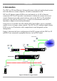
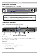
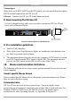
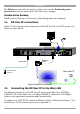
Table Of Contents
- 1. Welcome
- 2. Introduction
- 3. Features of DX User IP
- 4. DX User IP components
- 5. Cables
- 6. DX User IP front panel
- 7. DX User IP rear panel
- 8. Rack mounting the DX User IP
- 9. Pre-installation guidelines
- 10. Mouse synchronization limitations
- 11. DX User IP connections
- 12. Connecting the DX User IP to the Wan/LAN
- 13. Local User
- 14. Connecting an RS232 terminal
- 15. Order of powering on
- 16. Configuring the system
- 17. The DX User IP system interface
- 18. Logging in
- 19. Timeout
- 20. The Work area
- 21. Remote Console Settings
- 22. Telnet Console
- 23. Status via IPMI
- 24. Event Log via IPMI
- 25. File transfer – Virtual Floppy
- 26. Power Control
- 27. Keyboard & Mouse Settings
- 28. KVM Settings
- 29. KVM Port Settings
- 30. Video Settings
- 31. User/Group Management
- 32. User/Group Permissions
- 33. Network Settings
- 34. Dynamic DNS
- 35. Serial Port Settings
- 36. Security Settings
- 37. SNMP Settings
- 38. IPMI Settings
- 39. LDAP Settings
- 40. Maintenance
- 41. Accessing the remote console
- 42. Keyboard layout
- 43. The Control buttons /toolbar icons
- 44. The Chat window
- 45. The Video settings
- 46. Video Settings access
- 47. Mouse synchronization
- Frequently Asked Questions
- Glossary of terms
- Appendix A: DX User IP Video modes
- Appendix B: Key codes
- Appendix C: Pin assignments
- Appendix D: Disabling mouse acceleration
- Appendix E: Technical specifications
USER GUIDE
6
6. DX User IP front panel
Figure 2 illustrates the DX User IP front panel.
MINICOM
System OKActivity
DXU - IP
Figure 2 Front panel
The table below explains the functions of the front panel LEDs.
LED Function
Activity LED blinks when a remote user operates the DXU IP
System OK LED solid when DX User IP connected and functioning
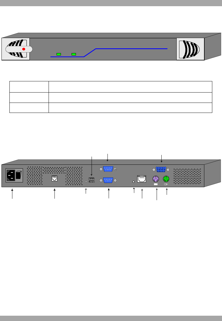
7. DX User IP rear panel
Figure 3 illustrates the rear panel of the DX User IP.
Power
connector
RS232 Serial
port
POWER
100-240 VAC 50/60 Hz
www.minicom.com
IP Reset
button
Ethernet
port
ETHERNET
SERIAL
I
0
SYSTEM
Keyboard
Mouse
Monitor
USBTERMINAL
USER
USB
ports
RS232
Terminal port
CAT5 to DX
Central
RST
DX Reset
button
Figure 3 DX User IP rear panel ports
Reset buttons
The DX Reset button resets the DX parts of the DX User IP. The IP Reset button
resets the IP parts of the DX User IP.
Serial port
Serial port is used as follows:
· Serial output for modem dial in connection
· Serial pass-through via Telnet
· Initial configuration