DX User IP User Guide w w w . m i n i c o m . c o m International HQ North American HQ European HQ Jerusalem, Israel Linden, NJ, USA Tel: + 972 2 535 9666 minicom@minicom.com Tel: + 1 908 4862100 info.usa@minicom.com Dübendorf, Switzerland Tel: + 41 44 823 8000 info.europe@minicom.com Customer support - support@minicom.com 5UM20140 V1.
DX USER IP Table of Contents 1. 2. 3. 4. 5. 6. 7. 8. 9. 10. 11. 12. 13. 14. 15. 16. 17. 18. 19. 20. 21. 22. 23. 24. 25. 26. 27. 28. 29. 30. 31. 32. 33. 34. 35. 36. 37. 38. 39. Welcome ................................................................................................................. 3 Introduction ............................................................................................................ 4 Features of DX User IP ...............................................................
USER GUIDE 40. 41. 42. 43. 44. 45. 46. 47. Maintenance ......................................................................................................... 50 Accessing the remote console............................................................................. 54 Keyboard layout ................................................................................................... 54 The Control buttons /toolbar icons ......................................................................
DX USER IP 1. Welcome Thank you for buying the DX User IP system. The DX User IP system is produced by Minicom Advanced Systems Limited. Technical precautions This equipment generates radio frequency energy and if not installed in accordance with the manufacturer’s instructions, may cause radio frequency interference. This equipment complies with Part 15, Subpart J of the FCC rules for a Class A computing device.
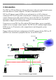
USER GUIDE 2. Introduction The DX User IP from Minicom Advanced Systems redirects local keyboard, mouse and video data to a remote computer. All data is transmitted via IP. DX User IP features remote KVM access and control via a LAN or Internet connection. DX User IP provides a non-intrusive solution for remote access and control.
DX USER IP 3. Features of DX User IP · KVM (keyboard, video, mouse) access over IP or analogous telephone line. · Automatically senses video resolution for best possible screen capture · High-performance mouse tracking and synchronization · Connect a user console for direct access to KVM switch · Local Mouse suppression (only when using SUN's Java Virtual Machine) DX User IP supports PS/2 type keyboards and mice and HD 15 video output. See the pin assignments in Appendix C. 4.
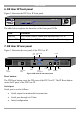
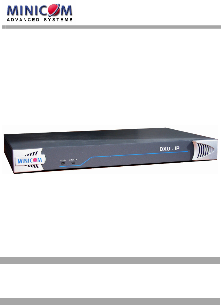
USER GUIDE 6. DX User IP front panel Figure 2 illustrates the DX User IP front panel. MINICOM DXU - IP Activity System OK Figure 2 Front panel The table below explains the functions of the front panel LEDs. LED Function Activity LED blinks when a remote user operates the DXU IP System OK LED solid when DX User IP connected and functioning 7. DX User IP rear panel Figure 3 illustrates the rear panel of the DX User IP. USB ports RS232 Serial port Monitor www.minicom.
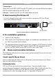
DX USER IP Terminal port When there are X-RICC RS232s in the DX system, you can control them through an RS232 terminal connected to the DX User IP. Ethernet - Connects the DX User IP to an Ethernet network. 8. Rack mounting the DX User IP Use the L-shaped brackets and screws provided to mount the DX User IP on a server rack as illustrated below. www.minicom.
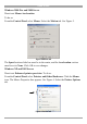
USER GUIDE Windows 2000 Pro and 2000 Server Deactivate Mouse Acceleration. To do so: From the Control Panel select Mouse. Select the Motion tab. See Figure 5. Figure 5 Motion tab The Speed section slider bar must be in the center, and the Acceleration section must be set to None. Click OK to save changes. Windows XP and 2003 Server Deactivate Enhanced pointer precision. To do so: From the Control Panel select Printers and Other Hardware. Click the Mouse icon. The Mouse Properties box appears.
DX USER IP The Motion section slider bar must be in the center, and the Enhanced pointer precision box must be unchecked. Click OK to save changes. Disable Active Desktop Disable Active Desktop, or do not use a plain background, use wallpaper. 11. DX User IP connections Figure 7 below illustrates the connections of the DX User IP to the DX system. See below for more details. P110 SD www.minicom.
USER GUIDE 10 Mbps connection For 10BASE-T Ethernet networks, the Fast Ethernet adapter uses Category 3, 4, or 5 UTP/FTP cable. To establish a 10 Mbps connection, the cable must be connected to a 10BASE-T hub. Ensure the cable is wired appropriately for a standard 10BASE-T adapter. Align the RJ-45 plug with the notch on the adapter's connector and insert it into the adapter's connector. 100 Mbps connection For 100BASE-TX Fast Ethernet networks, the DX User IP supports Category 5 UTP cabling.
DX USER IP 15. Order of powering on Connect the DX User IP to the power supply using the power cord provided. The devices and servers can be powered on at any time. Power on the DX components in the following order: 1. The primary and secondary level DX Centrals. 2. The DX User and DX User IP units. 16. Configuring the system The DX User IP's communication interfaces are based on TCP/IP, and it comes configured with the values listed below. · DHCP - disabled · IP address - 192.168.1.
USER GUIDE 1. Choose Start/Programs/Accessories/Communications/Hyperterminal. 2. When prompted enter a name and click OK. The Connect To box appears. See Figure 9. 3. Fill in the connection details. Select COM 1 in the Connect using box and click OK. The COM 1 properties box appears. See Figure 10.
DX USER IP 4. Set the port settings to the following values: · Bits/second - 115200 · Data bits - 8 · Parity - None · Stop bits - 1 · Flow Control - None 5. Click OK. The Hyperterminal appears. See Figure 11. Figure 11 The Hyperterminal 6. Press Enter. Some device information and a prompt appear. 7. Type config and press Enter. Configuration questions appear. DHCP must be disabled. You can change the IP address, net mask and default gateway.
USER GUIDE Via Ethernet Crossover connection Connect an Ethernet Crossover cable to the DX User IP and to the computer backto-back, the DX User IP is configured to 192.168.1.22, configure your computer to use a static IP in that range. For example 192.168.1.10. Open your browser and type 192.168.1.22. Configure the device via the WEB interface. Via the IP Device Setup utility The IP Device Setup utility is located on the supplied CD under Customer Support/Utilities.
DX USER IP This section deals with the HTTP interface. The other two interfaces are explained on pages 19 and 45. The Web browser must come with a Java Runtime Environment version 1.1 or higher. Without Java support, you can still maintain the remote host system using the administration forms displayed by the browser. We recommend the following browsers for an unsecured connection: · For Windows 98, ME, 2000 and XP, Microsoft Internet Explorer 5.
USER GUIDE Figure 14 The DX User IP Home page 19. Timeout After half an hour of non-activity the system automatically logs out. Clicking anywhere on the screen will lead back to the Login screen. 20. The Work area The Work area has a short summary about your DX User IP. · Server Power Status - On or Off · Firmware Version - installed on your DX User IP · Device management – self managed or connected to a management device · Users - all currently logged in users and IP addresses.
DX USER IP Figure 15 The Remote Console Settings All settings are user specific. Choose a user from the Drop-down menu. Transmission Encoding Transmission Encoding optimizes the speed of the remote screen depending on the number of parallel users and the bandwidth of the connection line. Automatic Detection - The encoding and the compression level is determined automatically from the available bandwidth and the current content of the video image. Pre-configured – Choose the connection method.
USER GUIDE Various Remote Console Options Start in Monitor Mode - Check this option to open the Remote Console window in read only mode. (No keyboard or mouse transferred to Host computer). Exclusive Access- Enables the Exclusive Access mode at Remote Console startup. This forces the Remote Consoles of all other users to close. No one can open the Remote Console until this user disables the Exclusive Access or logs off. Remote Console Type Default Java VM – Uses your Browser’s default Java Virtual Machine.
DX USER IP To require a confirmation request before keystrokes are sent, write confirm at the start. E.g. confirm Ctrl+Alt+Delete. For a list of key codes and aliases DX User IP recognizes, refer to Appendix B on page 63. Press Apply for the changes to take effect. Home Page Refresh – Refreshes the DX User IP Home page, so that direct Smart IP Links updates their status. 22. Telnet Console The Telnet Console offers a Java applet for the Telnet protocol to open a connection to DX User IP.
USER GUIDE quit - Logs out current user and disconnects from the client. version - Shows all available version numbers terminal - Starts the terminal passthrough mode for serial port 1. The key sequence ` exit' switches back to command modus. 23. Status via IPMI The Status via IPMI function shows the current values and the min/max-thresholds of all fans, temperatures and voltages existing in the host system. Change the thresholds by editing the values and pressing Apply.
DX USER IP Internal power Once connected, enable the internal power option using the Serial Port settings on page 40. The Power Control panel enables access to the most important external buttons of your host system. These buttons are the reset and the ATX power button. The power button represents the ATX power button on your host system. It is used to switch the power supply on and off. The ATX power button has 2 operation modes: a short press, and a press of about 4 seconds.
USER GUIDE External power If the external power option is enabled it will look like Figure 17. Figure 17 External power control The upper half is used to switch the power for the KVM port currently active. Use the KVM settings – see page 24 - to assign a port of the external power control to a KVM port. If no assignment exists, the option is disabled. The lower half offers controls for switching each port of the external power control directly.
DX USER IP Figure 18 Keyboard & Mouse Settings The elements of the Keyboard & Mouse Settings are explained below. Host Interface – Only Auto or PS/2 are active. USB is for future applications. Keyboard Model - Choose the keyboard model for the chosen port. Select Generic 106-key PC when connecting to computers with a Japanese OS. USB Mouse Type – Not active in the system, leave at the default state. Auto Mouse speed When Mouse Acceleration on the Host computer is enabled, check Auto Mouse speed.
USER GUIDE Figure 19 Mouse settings G&D Equalizer – This supports the mouse synchronization for Guntermann & Drunck KVM switches. These switches perform an internal rescaling of the mouse movements, which cause the existing algorithm to break if DX User IP is connected behind such a switch. This option detects the rescaling and compensates for it, so that the mouse synchronization works. Do not select this option for the DX User IPit may disrupt the normal mouse synchronization.
DX USER IP Figure 20 KVM Settings The elements of the KVM Settings are explained below. Active Port To switch to a computer: 1. Choose a number in the Active port Drop-down list. 2. Press . The computer screen appears in the Remote Console. Number of Ports To set the number of ports the KVM uses: 1. Choose a number in the Number of Ports Drop-down list. 2. Press . The number of rows chosen appears in the KVM Port Settings list. See Figure 21.
USER GUIDE Figure 21 KVM Port Settings 29. KVM Port Settings 1. Assign names for each port. 2. Define hotkeys to switch to each port. Choose either Minicom default hotkeys by selecting Minicom KVM-Switch in the Default configuration box, and then click the Set Defaults button. Or choose your own hotkeys. The syntax to define a new hotkey is as follows: [ + | - | * ] . For example LShift-LShift-*1-Enter. A + sign means that the keys are pressed together.
DX USER IP If an external power option is enabled it is possible to assign a port of this control for power switching to each KVM port, see page 20. Show in console – check this option to have a button with the port name appear on the top of the Remote console. Click the button to switch to that computer. Power Control – Click Assign to configure the power option for each port. The following screen appears. Figure 22 Power option Select the Serial port to which Power switch is connected.
USER GUIDE Each selection adds the outlet to the list at the bottom. The order of powering off/on, will be the order as set out in this list. Changing the order To change the order the outlets are powered on/off: Highlight the desired outlet and move it using the arrows. 30. Video Settings From the menu choose Video Settings. The Video settings appear. See Figure 23.
DX USER IP Custom Video Modes DX User IP recognizes a limited number of common video modes. When running X-Window on the host system, don't use any custom modelines with special video modes. If you do, DX User IP may not be able to detect these. Use any standard VESA video mode. Refer to Appendix A on page 62 for a list of all known modes. If your video mode differs from the standard VESA video mode, you can add up to 4 Custom Video Modes.
USER GUIDE Horizontal Frequency (Hz) - Horizontal (line) frequency. Vertical Frequency (Hz) - The vertical (refresh) frequency. Total horizontal pixels - The total amount of pixels per line, including non-visible and blank areas. Polarity - The polarity (positive/negative) of the synchronization signals. V means vertical, H means horizontal. Description Give the mode a name. The name appears in the Remote Console when the custom mode is activated. 31.
DX USER IP New user name Enter a login name for a new user here. Ensure that it is not the same as an existing user or group. Full user name Write the full name of the new user. Password / Confirm password The password must be at least four characters. Confirm password. Email address /Mobile number These are optional. Group membership/Member of/Not Member of Each user can be a member of one or more groups and inherit the rights of that group. Use the arrows to add or remove a user from a group.
USER GUIDE Modify User button To modify a user: 1. Select a user in the Existing users Drop-down list. 2. Click the lookup button to get all the user's information. 3. All fields can be modified as required. The old password is not displayed, but can be modified. 4. Click the Modify User button. Copy User To copy an existing user’s properties to a new user: 1. Select a user in the Existing user Drop-down list. 2. Enter a new user name in the New user name box. 3. Click the Copy User button.
DX USER IP Copy Group To create a group with the properties of an existing group: 1. Select a group in the Existing group Drop-down list. 2. Type a name into the New group name box. 3. Click the Copy Group button. 32. User/Group Permissions From the DX User IP Menu choose User/Group Permissions. The User/Group Permissions settings appear. See Figure 26. Figure 26 User/Group Permissions Each user or group has a set of access rights to the DX User IP functions.
USER GUIDE To change access rights: 1. From the Drop down list select a user/group. The selection list shows only users and groups, which you have the right to change. 2. Click the Update button. The access rights of the user appear. The meaning of the Permissions is as follows: Viewing a field. allow view means you can view it. deny access means you cannot view it. Changing a field setting. Allow change means you can change it.
DX USER IP Warning! Changing the network settings of DX User IP may result in losing the connection. If you remotely change the settings ensure that all values will give you access to the DX User IP. IP auto configuration Choose between the 3 options. None – no IP auto configuration. In this case type a static IP address in the appropriate settings below.
USER GUIDE Secondary Time Server This address will be used in case the Primary Time Server can't be contacted. Remote Console & HTTPS port Port number at which DX User IP's Remote Console server and HTTPS server are listening. If empty the default value is used. HTTP port Port number at which DX User IP's HTTP server is listening. If empty the default value is used. Telnet port Port number at which DX User IP's Telnet server is listening. If empty the default value is used.
DX USER IP DX User IP is reachable via the IP address of the DSL router, which is dynamically assigned by the provider. Since the administrator doesn't know the IP address assigned by the provider, DX User IP connects to a special dynamic DNS server in regular intervals and registers its IP address there. The administrator can contact this server as well and pick up the same IP address belonging to his card.
USER GUIDE Check interval - Interval for reporting again to the Dynamic DNS server by DX User IP. DX User IP has its own independent real time clock. Ensure the time setting is correct by configuring a timeserver see page 35. DX User IP registers itself to the Dynamic DNS server slightly different from the time configured. To reduce load peaks on the server we add a random time (0-10 min) to the absolute time value. 35. Serial Port Settings From the DX User IP Menu choose Serial Port Settings.
DX USER IP The DX User IP acts as an Internet Service Provider (ISP) to which you can dial in. The connection is established using the Point-to-Point Protocol (PPP). Before connecting to DX User IP, configure your console computer accordingly. For instance on Windows based operating systems you can configure a dial-up network connection, which defaults to the right settings like PPP. Serial line speed - Most modems today will support the default value of 115200 bps. For older modems lower the speed.
USER GUIDE Figure 31 External Power Option for Serial port 1 Serial Port 2 This port provides the power control options, see page 20. Choose a suitable setting and fill in additional required options. DX User IP supports the following: Internal Power Option - This option gives access to the ATX power and reset functions of a single connected system. You can change the duration of each button press. To do so, click Change button press durations. The box below appears. Adjust the time as desired.
DX USER IP Figure 33 Serial Port 2 external power option IPM 220-L (Inline Power Module) - External module option to switch power of a single system by putting it in the power supply line of the controlled system. SPC 800/1600 - Using the AvocentTM SPC, switch power for more than one system connected to DX User IP through a KVM switch. To use this device enter a username and password, which exist on the SPC and have the privileges to switch power for each port.
USER GUIDE Figure 34 Security Settings SSL settings Force HTTPS - Access the Web front-end only using an HTTPS connection. DX User IP won't listen on the HTTP port for incoming connections. KVM encryption - Controls the encrypting of the RFB protocol, used by the Remote Console to transmit the screen data to the administrator machine and keyboard and mouse data back to the host. Off - No encryption used. Try - Tries to make an encrypted connection. If unsuccessful, an unencrypted connection is used.
DX USER IP To create and install a DX User IP SSL certificate: 1. From the Security Settings page choose Create your own SSL certificate. The window appears as in Figure 35. Figure 35 CSR 2. Fill in the fields: Common name - Network name of DX User IP once installed in the user's network. It is identical to the name that is used to access the card with a Web browser.
USER GUIDE Key length - Length of the generated key in bits. 1024 Bits are supposed be sufficient for most cases. Larger keys may result in slower response time during the connection. 3. Click . 4. Press Download CSR to download the CSR to your administration machine. 5. Send the CSR to a CA for certification. They will send a new certificate 6. Press Upload to upload the certificate to DX User IP. The certificate uploads.
DX USER IP 0.0.0.0/0 matches any IP packet. Policy - Determines what to do with matching packets. They are accepted or dropped. NOTE: The order of the rules is important. The rules are checked in ascending order until a rule matches. Rules below the matching one are ignored. The default policy applies if no match has been found. Append a rule – To add a rule to the end of the rule list: Enter the IP/Mask and set the policy. Then press .
USER GUIDE · Server's power state · The following actions can be initiated via SNMP: · Reset server · Power on/off server · Reset DX User IP The following events are reported by DX User IP via SNMP: · Login trial at DX User IP failed · Login trial at DX User IP succeeded · Denying access to a particular action. · Server was reset. · Server was powered on/off From the DX User IP Menu choose SNMP settings. The SNMP Settings appear. See Figure 36.
DX USER IP Write Community - This community allows you to set options and reset DX User IP or the host via SNMP. System Location - Type a description of the physical location of the host. This will be used in reply to the SNMP request "sysLocation.0". System Contact - Type a contact person for the host. This will be used in reply to the SNMP request "sysContact.0".
USER GUIDE From the DX User IP Menu choose IPMI Settings. The IPMI Settings appears. See Figure 37. Figure 37 IPMI Settings IPMI disabled - Disables IPMI. Status via IPMI and Event Log via IPMI are not available and the power on/off and reset functions won't use IPMI. BMC address - Hexadecimal Baseboard Management Controller address. Needed for all types of communication to the IPMI-interface. Usually you can find this address in the BIOS of the host system. The default and common value is 20.
DX USER IP 39. LDAP Settings You can keep authentication information in a central LDAP directory. The purpose of LDAP is simply to confirm the password during login with the LDAP server. The user must exist on both the LDAP and Smart IP 16 side. On login Smart IP 16 internal user management checks the user. If the user is verified the password is then checked against the LDAP server.
USER GUIDE Name of user-entry object class - The object class that identifies a user in the LDAP directory. To use the default leave this field empty. The default depends on the selected LDAP server type. User search subfilter - Refine the search for users that should be known to the DX User IP. 40. Maintenance From the DX User IP Menu choose Maintenance. The DX User IP Maintenance window appears. Board Summary - This contains information about the DX User IP and its current firmware.
DX USER IP Attention: Only experienced staff members or administrators should perform a firmware update. Direct SmartIP Links You can set up direct links to any Minicom IP hardware over a LAN or WAN. Use the links to directly connect to these IP units without having to remember their IP addresses. You can also see the status of the remote IP units as explained below. All the IP units must have firmware that supports direct connection functionality.
USER GUIDE 4. In the Device Name column type a description. 5. Click Apply. On the Home page Monitor icons representing the direct connection IP units appear. See Figure 42.
DX USER IP Direct Connection Links for all Minicom IP Solutions On-Line Status and Direct Links to all Minicom IP products in organization. LAN or WAN CAT5 SM A R T PHANTO M M X IP Remote Administrator GI F Activ ity Sys te m O K M INI CO M Phantom MX IP Factory RESET SM A R T S WIT CH IP GI F MI NICOM VR E www.m inico m.
USER GUIDE 41. Accessing the remote console From the menu click Show Remote Console. The DX Login screen appears inside the remote console. See Figure 44. Figure 44 The DX Login screen inside the remote console Go to the DX Operating Guide Type the default username ‘admin’ and password ‘admin’. To configure/manage the devices connected to the DX system see the DX Operating Guide. You can work on the remote console with the keyboard and mouse.
DX USER IP The Remote Console window is a Java Applet that tries to establish its own TCP connection to DX User IP. The protocol that is run over this connection is not HTTP or HTTPS but a protocol called RFB (Remote Frame Buffer Protocol). Currently RFB tries to establish a connection to port number 443. Your local network environment must allow this connection to be made, i.e.
USER GUIDE Exclusive access - If a user has the appropriate permission, he can force the Remote Consoles of all other users to close. No one can open the Remote Console until this user disables the Exclusive access or logs off. Readability Filter - Turn the filter on in scaling mode to preserve most of the screen details. Only available with a Java Virtual Machine version number of 1.3 or higher. Scaling - Scale down the Remote Console. Not all display details will be preserved.
DX USER IP Information bar - Shows the console and connection state and remote screen size. The value in round brackets describes the connection to the remote system: Norm stands for a standard connection without encryption; SSL stands for a secured connection. Double click the bar to see a history of all the status information. 44. The Chat window Use the Chat window to chat with others logged into the system. Figure 45 illustrates the Chat window.
USER GUIDE The parameters have the following functions: Brightness - Brightness control. Contrast Red/Green/Blue- RGB contrast control. Clock - Sets the horizontal frequency for a video line, this depends on the video mode. Different video cards may require different values. The default settings and auto adjustment procedure should be adequate for all common configurations. If not change this setting together with the sampling phase. Phase - Sets the phase for video sampling.
DX USER IP Intelligent Sync - If fast sync doesn't work or the mouse settings have been changed on the host system use the Intelligent Sync option. To do so: 1. Ensure the picture is correctly adjusted, Click Auto Adjust or manually correct the picture using the Video Settings. 2. Choose Options / Mouse Handling / Intelligent Sync. Pressing the recently changed. button leads to a fast sync, except when the video mode Note! For the intelligent sync to work, the picture MUST be correctly adjusted.
USER GUIDE F r eq u e n t l y A s k ed Q u es t i o n s Q 1: The client mouse doesn't work or is not synchronized. A: Ensure the DX User IP mouse settings match the mouse model. Also see page 58 Q 2: Bad video quality or grainy picture A: Use the brightness and contrast settings - see page 57. Use the auto adjustment feature to correct a flickering video. Q 3: Login fails. A: Was the correct user and password given? On delivery, the user "super" has the password "smart".
DX USER IP Gl o s s a r y o f t er ms ACPI - A specification that enables the operating system to implement power management and system configuration. ATX - Advanced Technology Extended: A particular specification of a motherboard introduced by Intel in 1995. BMC - Board Management Controller: implements the IPMI based main board management functions. DHCP - Dynamic Host Configuration Protocol: protocol for dynamically assigning IP configurations in local networks.
USER GUIDE A p p e n d i x A : D X U s er I P V i d e o m o d es The DX User IP supports the following video modes. Do not use other custom video settings.
DX USER IP A p p e n d i x B : K e y c o d es Figure 47 illustrates the keys on a standard 104 key PC keyboard with a US English language mapping. These keys are used to define keystrokes or hotkeys for several DX User IP functions. The keys may not represent keys used on international keyboards. Most modifier keys and other alphanumeric keys are in identical positions, whichever language mapping you are using.
USER GUIDE Key Psc Scrl Brk Ins Pos1 Pup Del Pdn Key code PRINTSCREEN SCROLL_LOCK BREAK INSERT HOME PAGE_UP DELETE PAGE_DOWN UP LEFT DOWN RIGHT The numerical keypad codes Key Key code num NUM_LOCK 0 NUMPAD0 1 NUMPAD1 2 NUMPAD2 3 NUMPAD3 4 NUMPAD4 5 NUMPAD5 6 NUMPAD6 7 NUMPAD7 8 NUMPAD8 9 NUMPAD9 + NUMPADPLUS / NUMPAD/ * NUMPADMUL NUMPADMINUS CR NUMPADENTER 64 Alternative Alternative NUMPAD_PLUS NUMPAD_MUL NUMPAD_MINUS
DX USER IP Appendix C: Pin assignments VGA HD-15 5 4 10 3 9 2 8 1 7 6 15 14 13 12 11 Pin 1 2 3 4 5 6 7 8 Assignment Red Green Blue Not connected GND GND red GND green GND blue Pin 9 10 11 12 13 14 15 Assignment 5V GND sync Not connected SDA, DCC, ...
USER GUIDE Serial SUB-D 9 Connector 1 2 6 Pin 1 2 3 4 5 3 7 4 8 Assignment DCD RX TX DTR GND 5 9 Pin 6 7 8 9 66 Assignment DSR RTS CTS RI
DX USER IP A p p e n d i x D : D i s a b l i n g mo u s e a c c el e r a t i o n The following steps describe how to disable mouse acceleration in a number of different Operating Systems. Windows 98 and Windows ME 1. From the Control Panel, click the Mouse icon. 2. From the Mouse Properties dialog box, click the Pointer Options tab. 3. Center the Pointer Speed slider bar 4. Click the Accelerate… button. 5. Deselect Pointer acceleration option. Windows 98 SE and Windows NT4 1.
USER GUIDE Linux 1. Execute the following command line parameter: xset 0 255 2.
DX USER IP A p p e n d i x E : T ec h n i c a l s p ec i f i c a t i o n s Host computer Operating systems Novel, Linux, Windows 98, 2000, XP and later Client computer Operating systems Windows 98, ME, 2000, XP and later, Linux. Internet browser with full Java support.
USER GUIDE User Guide Feedback Your feedback is very important to help us improve our documentation. Please email any comments to: ug.comments@minicom.com Please include the following information: Guide name, part number and version number (as appears on the front cover). E.g.
DX USER IP Regional Offices Germany France Italy Kiel Vincennes Rome Tel: + 49 431 668 7933 info.germany@minicom.com Tel: + 33 1 49 57 00 00 info.france@minicom.com Tel: + 39 06 8209 7902 info.italy@minicom.com www.minicom.