
User guide


12
13
14
15
Connector
Function
Serial
This port is for future Serial
functionality
Flash
To update firmware of the analogue part of the 116 IP
Switch
system - OSD, Switch,
ROCs.
LAN
Connect to 10/100 Mbit Ethernet. Green LED illuminates
when
unit is connected to a 100 Mbit/sec network. Yellow
Led
illuminates when unit is connected to a 10 Mbit/sec
network.
Server
ports
Connect to servers via
ROCs
QUICK S
T
A
R
T
GUI
D
E
2. Slide the Switch 116 IP into the rail and into the back of the SmartRack console
until you hear a click. See the figure below.
S
M
A
R
T
R
A
C
K
116
IP
6. The SmartRack Switch system
configuration
You connect servers to the 116IP switch via ROCs. Figure 17 illustrate the basic
configuration of the 116IP system.
QUICK S
T
A
R
T
GUI
D
E
6.2 Connecting ROCs to servers
Each computer/server is directly connected to the SmartRack switch via the
appropriate ROC using CAT5 cable in a star configuration. No external power is
needed at the remote ROCs. The ROCs draw their power from the computer’s
keyboard port (ROC PS/2) or from the USB port (ROC USB).
6.2.1 Connecting a ROC PS/2
You can connect the ROC PS/2 to a powered on computer, but it must be in the
following order:
S
M
A
R
T
R
A
C
K
11
6
IP
7. Initial settings - Default IP
address
The following sections provide instructions for setting the IP address for the
SmartRack 116 IP unit.
By default, SmartRack 116 IP boots with an automatically assigned IP address
from a DHCP (Dynamic Host Configuration Protocol) server on the network. The
DHCP server provides a valid IP address, gateway address and subnet mask.
To identify the IP address, the SmartRack 116 IP MAC address appears on the
underside of the SmartRack 116 IP box. The device number (D.N.) can also be
MINICOM
SERIAL 9 10 11 12 13 14 15 16
Figure 15 Slide switch into back of SmartRack
3. Secure the Switch 116 IP to the rail by inserting the thumbscrews through the
bracket and into the rail and tightening them, see Figure 16.
User over IP
SMARTRACK 116IP SWITCH
FLASH
LAN
1
2
3
4
5
6
7
8
SMARTRACK 116IP SWITCH
Internet / VPN / LAN
To servers
CAT5
cables
Up to 30M /
100ft
ROCs
to servers
1. Connect the Mouse connector to the computer’s Mouse port.
2. Connect the Keyboard connector to the computer’s Keyboard port.
3. Connect the Screen connector to the computer’s Video port.
Failure to connect in the above order while the server is running, may lead to the
mouse malfunctioning until the server is rebooted.
6.2.2 Connecting a ROC USB
The ROC USB supports Windows 98 SE and later, MAC, SUN, SGI and all
modern Linux distributions.
found there.
If no DHCP server is found on the network, SmartRack 116 IP boots with the static
IP address:192.168.0.155.
Note! If a DHCP server later becomes available, the unit picks up the IP settings
from DHCP server. To keep the static IP address, disable DHCP – explained in the
softcopy User Guide.
7.1 Static IP addresses for a number of units
Where you want to connect more than 1 SmartRack 116 IP to the same network
and there is no DHCP server, or you want to use static IP addresses, do the
Figure 16 Tightening the thumbscrews
Figure 17 SmartRack 116IP Switch system configuration
6.1 The 116 switch
To connect the ROC USB:
1. Connect the Screen connector to the computer’s Video port.
2. Connect the USB connector to the computer’s USB port.
following:
Connect the SmartRack 116 IP units one at a time and change the static IP address
of each unit before connecting the next unit.
MINICOM
SERIAL 9 10 11 12 13 14 15 16
6.3 Connecting to the network
8. Logging into the Web
interface
SMARTRACK116IP
SWITCH
FLASH LAN
Flash
1 2 3 4 5 6 7 8
Connect the network cable to the LAN port. This must be done before powering on
the SmartRack 116IP Switch.
Client computer operating system. - Windows 2000 or higher, with Firefox 3 or
Internet Explorer 7.0 or later version. Linux with Firefox 3.
(download)
LAN (Ethernet)
connector
connector
Server ports
Power
connector
6.4 Connecting the CAT5 cables
Complete the initial setup via the Web configuration interface:
6.1.1 Connector table
Figure 18 116IP Switch ports
1. Connect one connector to the ROC’s RJ45 port.
2. Connect the other connector to one of the SmartRack Switch Server ports.
3. Follow the above 2 steps for each computer.
6.5 Connecting the power
supply
1. Connect the switch to the power supply using the Power cord provided. Only
use the Power cord supplied with the unit.
2. Power on the switch.
1. Open your Web browser and type the SmartRack 116 IP system IP address -
https://IP address/ - and press Enter. The login page appears.
2. In mode select Configuration mode..
3. Type the default Administrator user name admin and password access (both
lower case).
8
9
10
11
QUICK START GUIDE
4. Press Enter. The Web interface opens at the Network Configuration page, see
Figure 19.
SMARTRACK 116 IP
9.1.2 Selecting a computer
To select a computer:
QUICK START GUIDE
10. Starting a remote
session
SMARTRACK 116 IP
1. Navigate to the desired computer line.
Or, type the port number of the desired computer.
At a Client computer open the web browser and type the SmartRack 116 IP’s IP
address. https://IP address. The Login page appears. Type your username and
password and press Enter. By default, the user name is: admin and the password is
Locks
Toolbar
Session
Profile
Video
Settings
Power Control
Settings
Keyboard
Settings
Mouse
Settings
Full
Screen
Mode
Disconnect
Session
access, (both lower case).
(Currently not
operational)
Target Switching
Menu
9. The
OSD
To display the OSD:
Figure 19 SmartRack 116 IP Web interface
2. Press Enter. The selected computer is accessed. A confirmation label appears
showing which computer is accessed.
Note! When the OSD is displayed you cannot select computers using the
keyboard hotkeys.
Note! There is a shortcut to the Configuration pages from the login page. In mode
you can toggle between the option to access a remote session or the configuration
pages.
When connecting you will download the Java client..
.
The screen of the currently selected Target Server with Minicom toolbar appears
see Figure 21.
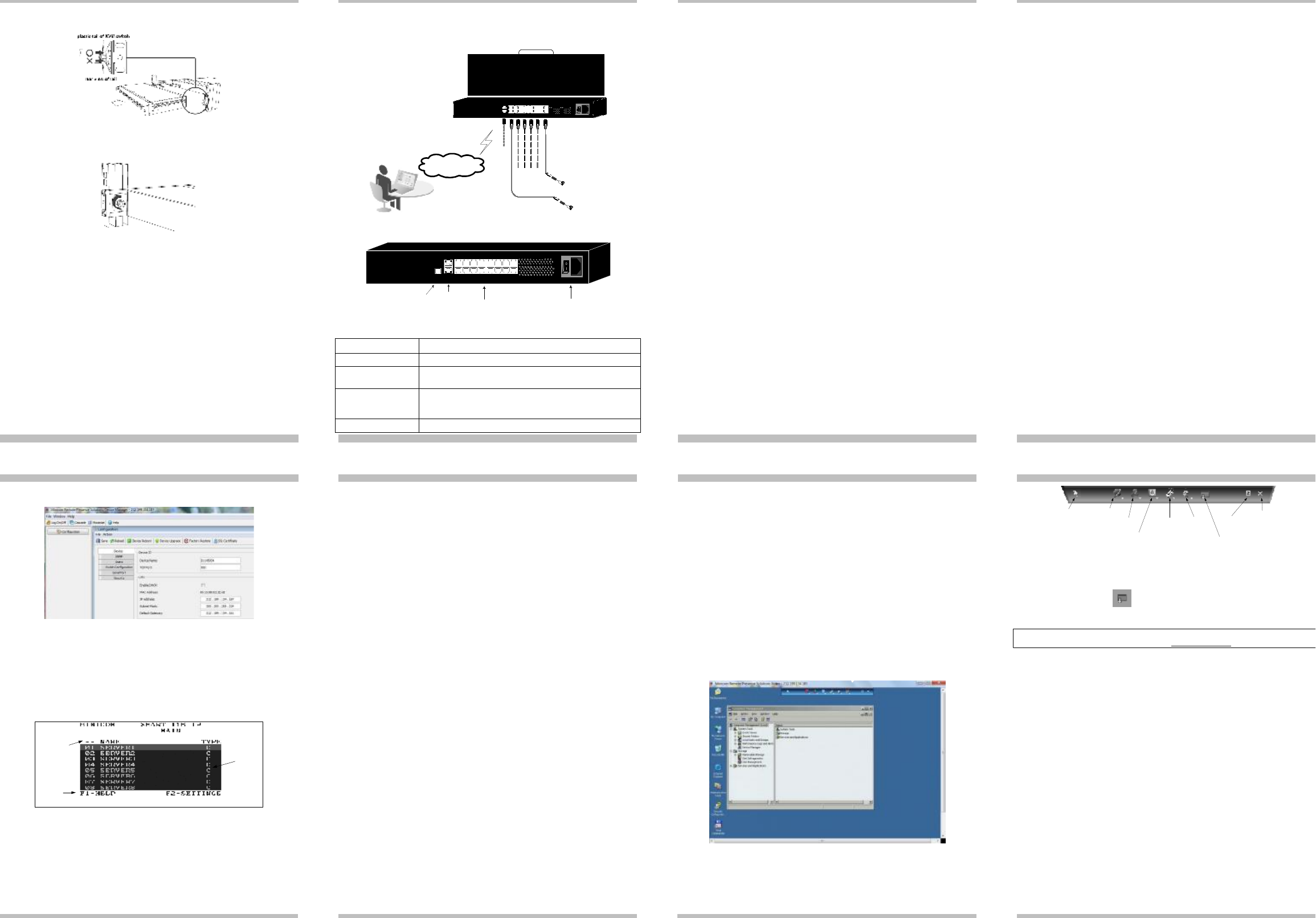
Figure 22 Toolbar icons
10.1 Switching to a different server/device
To connect to a different server/device:
1. From the Toolbar, click . A list of connected servers/devices appears.
2. Click the desired server. The screen of the server appears.
To complete the initial setup and log into the web interface please see the softcopy
User
Guide on the supplied CD or on our website
www.minicom.com
in the Support
section.
1. Ensure there is no remote user connected. To disconnect the remote user press
the Local button on the SmartRack 116 IP.
2. Press Shift twice. The OSD Main window appears. See Figure 20. Lines with
yellow text show active computers. Lines with blue text show inactive
computers. The Type column indicates a computer “C” is connected to the port.
Port number
Server name
Toolbar
appears here
C=computer
Instruction
keys
Figure 20 OSD Main window
9.1.1 Navigating the OSD
To navigate up and down use the Up and Down arrow keys.
To jump from one column to the next (when relevant) use the Tab key.
To exit the OSD or return to a previous window within the OSD press Esc.
Figure 21 Remote console window