SmartRack 116 IP User Guide w w w . m i n i c o m . c o m International HQ North American HQ European HQ Jerusalem, Israel Linden, NJ, USA Dübendorf, Switzerland Tel: + 972 2 535 9666 minicom@minicom.com Tel: + 1 908 486 2100 info.usa@minicom.com Tel: + 41 44 823 8000 info.europe@minicom.com Technical support - support@minicom.com 5UM20182 V1.
SMARTRACK 116 IP Table of Contents 1. Welcome ...................................................................................................................... 4 Section I ........................................................................................... 5 2. Introduction ................................................................................................................. 5 2.1 Key features ..........................................................................................
USER GUIDE 20. Saving changes and logging out............................................................................. 31 21. Starting a remote session ....................................................................................... 31 21.1 Taking over a busy remote session................................................................................................ 33 21.2 The Toolbar .............................................................................................................
SMARTRACK 116 IP 25.4.3 Updating the firmware ............................................................................................................ 59 25.4.4 Manually updating ROCs ....................................................................................................... 60 25.5 Troubleshooting the Update software ............................................................................................ 60 25.5.1 Resetting through the Update software ...................................
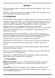
USER GUIDE 1. Welcome Thank you for buying the SmartRack 116 IP system. This system is produced by Minicom Advanced Systems Limited. This document provides installation and operation instructions for Minicom’s SmartRack 116 IP. It is intended for system administrators and network managers, and assumes that readers have a general understanding of networks, hardware and software.
SMARTRACK 116 IP Section I This section explains how to configure and operate the SmartRack 116 IP system remotely over IP. Section II on page 46, explains how to operate the Smart 16 IP switching system locally through the On Screen Display (OSD). 2. Introduction The SmartRack 116 IP extends your KVM (keyboard, video, and mouse) from any computer or server over TCP/IP via LAN, WAN or Internet connection.
USER GUIDE Web-based control - Browser control to a target server, from any location via secured standard IP connection. Multi-user view mode - Allows simultaneous users to view remote sessions. Remote control can be intuitively handed between users with appropriate permissions. Security - Supports the highest security standards for encryption (128 bit SSL and HTTPS) and authentication for remote user and advanced OSD management with multi-layer security for local user. KVM.
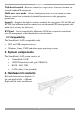
SMARTRACK 116 IP Long bracket x 2. (For increased rack depth of 905 ~ 990mm) Short bracket x 2 Bracket attachment x 2 Note! The short bracket and bracket attachment for a rack depth of 504~ 614 mm and without a KVM switch connected to the drawer. Flat screws x 6 (for rail mount to console body) Screws x 6 Bracket A with thumbscrew x 2 Screws x4 Keys x 2. 5.
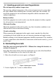
USER GUIDE 5.1 Avoiding general rack mounting problems Elevated operating ambient temperature The operating ambient temperature of the rack environment may be greater than the room ambient when installing into a closed or multi-unit rack assembly. So install the equipment in an environment compatible with the maximum rated ambient temperature. Reduced airflow Install the equipment in a rack in such a way that the amount of airflow required for safe operation is not compromised.
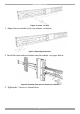
SMARTRACK 116 IP Figure 2 Loosen 7 screws 3. Adjust the rear bracket to fit your cabinet, see below. Figure 3 Adjusting the bracket 4. Install the front and rear bracket onto the cabinet, see figure below. Figure 4 Installing front and rear bracket on cabinet 5. Tighten the 7 screws as shown below.
USER GUIDE Figure 5 Tightening the 7 screws 6. Repeat the steps above to connect the other rail to the other side of the rack. 7. Slide the SmartRack console between the rails as shown below. Figure 6 Sliding the SmartRack between the rails 8. Unlock and pull both left and right rail–lock switches together – see below – and push the console all the way into the rack. Figure 7 Rail–lock switch 9. Connect three flat screws to the rear of the console on both sides. See figure below.
SMARTRACK 116 IP Figure 8 Connecting three flat screws to the rear of the console The console now sits snugly in the rack, see Figure 9. Figure 9 Console in the rack 6.1 Using the longer bracket for rack depth of 905 ~ 990mm To replace the bracket with the longer bracket: 1. Loosen the 7 screws as shown below. Figure 10 Loosening the 7 screws Remove the six (different) screws as shown below.
USER GUIDE Figure 11 Removing the six screws 2. Take the rear bracket out, see below. Figure 12 Taking the rear bracket out 3. Insert the long bracket into the rail then adjust the bracket to fit your cabinet. Tighten at least 2~3 screws along the length you need. See Figure 13. Figure 13 Inserting and tightening the long bracket 4. Repeat the above steps for the other side. 5. Go to section 6 Connecting to a rack. 6.2 Connecting the KVM Switch 116 IP 1.
SMARTRACK 116 IP Figure 14 Connecting the bracket A to the sides of the Switch 2. Slide the Switch 116 IP into the rail and into the back of the SmartRack console until you hear a click. See the figure below. Figure 15 Slide switch into back of SmartRack 3. Secure the Switch 116 IP to the rail by inserting the thumbscrews through the bracket and into the rail and tightening them, see Figure 16.
USER GUIDE 7. The SmartRack Switch system configuration You connect servers to the 116IP switch via ROCs. Figure 17 illustrate the basic configuration of the 116IP system. SERIAL MINICOM 9 10 11 12 13 14 15 16 1 2 3 4 5 6 7 8 I 0 SMARTRACK 116IP SWITCH FLASH LAN SMARTRACK 116IP SWITCH CAT5 cables Up to 30M / 100ft User over IP Internet / VPN / LAN To servers ROCs to servers Figure 17 SmartRack 116IP Switch system configuration 7.
SMARTRACK 116 IP 7.1.1 Connector table Connector Function Serial This port is for future Serial functionality Flash To update firmware of the analogue part of the 116 IP Switch system - OSD, Switch, ROCs. LAN Connect to 10/100 Mbit Ethernet. Yellow Led illuminates when connected to LAN. Green LED illuminates when a remote session is in progress Server ports Connect to servers via ROCs 7.
USER GUIDE 1. Connect the Mouse connector to the computer’s Mouse port. 2. Connect the Keyboard connector to the computer’s Keyboard port. 3. Connect the Screen connector to the computer’s Video port. Failure to connect in the above order while the server is running, may lead to the mouse malfunctioning until the server is rebooted.
SMARTRACK 116 IP 7.3 Connecting the CAT5 cables 1. Connect one connector to the ROC’s RJ45 port. 2. Connect the other connector to one of the SmartRack Switch Server ports. 3. Follow the above 2 steps for each computer. 7.4 Connecting to the network Connect the network cable to the LAN port. This must be done before powering on the SmartRack 116IP Switch. 7.5 Connecting the power supply 1. Connect the switch to the power supply using the Power cord provided.
USER GUIDE Note! If a DHCP server later becomes available, the unit picks up the IP settings from DHCP server. To keep the static IP address, disable DHCP – explained in section 11.1 on page 21. 9.
SMARTRACK 116 IP Unit boots up Device network setting is set to obtain IP address from DHCP Server Yes Every 5 minutes Is DHCP Server present in the connected LAN? No Device IP is: 192.168.0.155 No Yes IP address is assigned by the DHCP server No To access the configuration page of the unit, open IE 6.
USER GUIDE 10. Logging into the Web interface Client computer operating system. Windows 2000 or higher, with Internet Explorer 6.0 or later version. 128 bit encryption support is required. Complete the initial setup via the Web configuration interface: 1. Open your Web browser (Internet Explorer version 6.0 or higher). 2. Type the SmartRack 116 IP system IP address - https://IP address/config - and press Enter. The login page appears, see Figure 24. Figure 24 Login page 3.
SMARTRACK 116 IP The first warning disappears upon first SmartRack 116 IP client installation, when Minicom’s root certificate is installed. 11. Network > Configuration Consult your Network Administrator for the network settings. Device name - Type a name for the SmartRack 116 IP. Default device name consists of the letter ‘D’ followed by the 6-digit device number (D.N.) found on the silver label on the underside of the SmartRack 116 IP box. 3 TCP Ports - Choose any 3 TCP ports from port #800 to 65535.
USER GUIDE 11.2 KVM.net KVM.net is a centralized IP based system for secure control of servers and network devices, power and user administration in the data center environment. KVM.net combines Out-Of-Band, KVM via IP access with modern IT standards and requirements. It is the most comprehensive remote server maintenance solution available in the market today. Enable KVM.net - Check this option to allow SmartRack 116 IP unit to be remotely managed by Minicom’s KVM.net system.
SMARTRACK 116 IP 12.1 SNMP Events table The table below list all events recorded. Event Text Code Comment "System Boot" 1010 Reported upon device boot up. nd "Server Busy ask 1030 for disconnect..." Attempt to connect when another user is already connected. The 2 user has nd permission for takeover, sent before the 2 user actually takes over the session. "User login succeeded" 1040 On every successful user login to the device.
USER GUIDE Event Text Code Comment Login is not successful because server is busy. 2040 Login is not successful because server is busy.
SMARTRACK 116 IP 13. Administration > User Settings From the menu click User Settings, Figure 27 appears. Figure 27 User Settings On this page an Administrator creates and edits users. There are 3 levels of user access: • Administrator • User • View only Administrator An Administrator has unrestricted access to all windows and settings and can “take over” any active session (explained in section 21.1 on page 33).
USER GUIDE 13.1 Adding a user To add a user: and type a name and a password. The password must be at 1. Click least 6 characters – letters or numbers, and must not include the user name, even if other characters are added. Note! The following “special” characters: &, <, >, ”, {, } cannot be used for either the user name or password. Depending on the security level chosen the user name and password parameters are different. See section 16 on page 28. 2. Select the permission type from the Permission box. 3.
SMARTRACK 116 IP 14. Administration > Switch Configuration Give the servers connected to the SmartRack 116 IP unique names, so that users accessing the system can identify the servers easily. To do so: 1. From the menu click Switch Configuration. The Switch Configuration window appears, see Figure 28. Figure 28 Switch Configuration 2. In the Server Name section change the name of the connected servers by selecting the server name and typing a new name. Click changes.
USER GUIDE Figure 29 User Targets Configuration 2. Select a user from the User drop-down menu. 3. Check the Target servers the user can access (according to his access permissions). To select all Target servers, press Select All. 4. Click Apply, the selection is saved. 5. Repeat the above steps for other users. 16. Security > Settings Configure the security features, such as Account Blocking, Password Policy and Idle Timeout, as explained below.
SMARTRACK 116 IP Password Policy – You have the option of a standard or high security level of password. The table below shows the parameters of the 2 options. Standard security policy High security policy 6 characters or more 8 characters or more must include at least 1 digit and 1 upper case letter and 1 “special” character as follows !@#$%^*()_-+=[]’:;?/ Must not include the user name Must not include the user name Check the box to enable the high security password policy.
USER GUIDE 18. Maintenance > Firmware Upgrade Upgrade the SmartRack 116 IP firmware to take advantage of new features. Download the firmware from the Support section of Minicom’s website – www.minicom.com. Save the firmware file on the Client computer. From the menu select Firmware Upgrade. The Firmware Upgrade window appears showing the current firmware version see Figure 32. Figure 32 Firmware Upgrade 1. Locate and upload the firmware file. 2. Verify the current and uploaded version of the firmware. 3.
SMARTRACK 116 IP Figure 33 Restore factory settings 2. Check the box if you want to preserve Network settings. 3. Click . 20. Saving changes and logging out To save any configuration changes and restart the SmartRack 116 IP click . You must press after making changes to the following pages: • Network>Configuration • Network>SNMP Settings • Security>Settings • Security>SSL Certificate To exit the Configuration menu and close the session, click .
USER GUIDE Figure 34 Select Run as administrator On first connection install the Minicom certificate and ActiveX control. You must login as an Administrator to your computer to install the ActiveX control. Once the ActiveX control is installed, all types of users can login. On connecting, the screen of the lowest numbered Target Server that the user has permission to access appears. Figure 35 illustrates the remote session window.
SMARTRACK 116 IP On the remote console you have the following: Server Confirmation label – This confirms the identity of the current server accessed and disappears by default after 30 seconds, (this period can be adjusted in the OSD – explained in Section II of the guide). It appears again when switching to a different server. The currently accessed server identity can be checked any time by looking at the Server name on the Internet Explorer title bar.
USER GUIDE To hide the Toolbar, either: Double-click the SmartRack 116 IP System tray icon . Or Press F9. To display the Toolbar repeat the above action. See also page 42. 21.3 Switching to a different server To connect to a different server: 1. From the Toolbar, click , or right-click . A list of available servers appears. The currently connected server is highlighted in bold. 2. Click the desired server name. The screen of the selected server appears. 21.
SMARTRACK 116 IP Low - Select Low for high compression and 16 colors. Medium - Select medium for medium compression and 256 colors. Medium is recommended when using a standard internet connection. High - For optimal performance when working on a LAN, select High. This gives a low compression and high colors (16bit). Custom – You cam choose your own compression and color levels. Click OK. The screen of the last accessed Target Server appears. 21.
USER GUIDE Figure 38 Manual Video Adjustments controls Brightness / Contrast - use the scales to adjust the brightness and contrast of the displayed image. Move the sliders to change the displayed image. Click in the area of the sliders for fine-tuning. For the following controls choose the appropriate measurement. Horizontal Offset - defines the starting position of each line on the displayed image. Vertical Offset - defines the vertical starting position of the displayed image.
SMARTRACK 116 IP 21.6 Power cycle This button . is for future Serial power management options. 21.7 Keyboard key sequences Click . A list of defined keyboard sequences appears. When clicked, these transmit directly to the Target Server, and will not affect the Client computer. For example, select Ctrl-Alt-Del to send this three key sequence to the Target Server to initiate its Shutdown/Login process. To add a keyboard sequence: Click Add/Remove. The Special Key Manager box appears see Figure 39.
USER GUIDE Figure 40 Add Special Key Dialog box 2. Give the key sequence a name in the Label field. 3. Click Start Recording. 4. Press the desired keys. The key sequence appears in the area provided. 5. Click Stop Recording. 6. Click OK. To edit a key sequence: 1. From the Special Key Manager Dialog box select the desired key. 2. Click Edit. 3. Click Start Recording 4. Press the desired keys. The keys appear in the area provided. 5. Click Stop Recording. 6. Click OK. 21.
SMARTRACK 116 IP 21.8.1 Aligning the mice pointers When accessing the Target Server, the mice may appear at a distance to each other. To align the mouse pointers: From the Toolbar click align. / Align or press Ctrl+M simultaneously. The mice 21.8.2 Calibrating mice pointers A Target Server may have a different mouse pointer speed to the Client computer. Calibrating automatically discovers the mouse speed of the Target Server and aligns the two pointers.
USER GUIDE Figure 41 Mouse Settings Dialog box 2. Select the Target Server’s Operating System and click OK. Instructions and sliders appear. 3. Follow the instructions and set any relevant sliders to the same values as set in the Target Server’s Mouse Properties window. 2 examples! For Windows XP, 2003 Server, Vista and 2008 Server. Go to the Mouse settings on the Target Server and uncheck Enhance pointer precision. For Windows NT4, 98, ME, 2000.
SMARTRACK 116 IP Figure 42 Mouse Emulation Dialog box Select the mouse connected to the Local Console port on the SmartRack 116 IP, e.g. if the local mouse is a 2 button mouse, select Standard Mouse. Max Rate - this defines the maximum mouse report rate. For Sun Solaris the default value is 20 in order to support older Sun versions. 21.9 Minicom icon menu features , a menu appears. From this menu you can Right-click the Minicom icon access the connected devices.
USER GUIDE Full Screen Mode - Check this option to make the remote session screen appear in full screen mode from the next reconnection onwards. To toggle the full screen mode on and off, press F11. (Also see section below). Configuration – This only appears in the menu when an Administrator is logged in. Click Configuration to access the Web configuration interface. 21.10 Full screen mode Work on the Target Server as if you are working on a local computer, with full screen mode.
SMARTRACK 116 IP 22.1 Entering Safe mode To enter Safe mode: 1. Press and hold down the Local button for 3-4 seconds and at the same time power up the SmartRack 116 IP. The device boots up in Safe mode. 2. Wait until the unit finishes booting (1-2 minutes). 3. You need to know the IP address of the SmartRack 116 IP. The IP address depends on whether there is a DHCP server on the network. If there is, the DHCP server assigns an IP address to the SmartRack 116 IP.
USER GUIDE Figure 45 Login page 4. Type username: admin , password: SAFEmode. (Case sensitive). (This username and password works only in Safe mode). A menu appears, see Figure 46. Figure 46 Safe mode menu 22.2 Restoring factory defaults To restore factory defaults: 1. From the menu choose Restore Factory Settings. A warning appears see Figure 47. Figure 47 Warning 2. Click . A further warning appears, see below.
SMARTRACK 116 IP Figure 48 Warning 3. Click OK, the factory defaults are restored. When the process finishes Figure 49 appears. Figure 49 Reboot 4. Click Reboot to restart the unit. 22.3 Restoring the device firmware Contact Minicom Technical Support support@minicom.com, to receive the Upgrade firmware required to restore the device firmware. Save the Upgrade firmware on the hard disk of a computer connected to the network. To restore the device firmware: 1.
USER GUIDE Section II Section II explains how to operate the SmartRack 116 IP Switching system locally (sections 23 and 24) and how to upgrade the SmartRack 116 IP firmware (section 25). Section 25.5 deals with troubleshooting. 23. Switching between computers Switch between the connected computers by either • Keyboard hotkeys • The OSD (On Screen Display) The OSD is also the place to adjust various settings as explained below.
SMARTRACK 116 IP Port number appears here C=computer Instruction keys Figure 51 OSD Main window 24.1.1 Navigating the OSD To navigate up and down use the Up and Down arrow keys. To jump from one column to the next (when relevant) use the Tab key. To exit the OSD or return to a previous window within the OSD press Esc. 24.1.2 Selecting a computer To select a computer: 1. Navigate to the desired computer line. Or, type the port number of the desired computer. 2. Press Enter.
USER GUIDE Note! When the OSD is password protected (explained below) only the Administrator has access to the F2 settings window. 24.1.4 The General settings With the GENERAL line highlighted, press Enter. The General settings window appears see Figure 53. Figure 53 General Settings window From this window you can do the following: 24.1.4.1 Security The OSD comes with an advanced password security system that contains 3 different security levels.
SMARTRACK 116 IP 24.1.4.4 User (Status U) There are 6 different Users in the SmartRack 116 IP system. Each User has a Profile set by the Administrator that defines the access level to different computers. There are 3 different access levels; these are explained on page 52. 24.1.4.5 Activating password protection By default OSD access is not password protected. Only the Administrator can password-protect the OSD or disable password protection. To do so: 1.
USER GUIDE 24.1.4.8 Changing the Keyboard language In the OSD the names of the computers can be written in 3 different languages – English (EN), German (DE), and French (FR). The keyboard is preset to English; this can be changed as follows: 1. Navigate to the Keyboard language line. 2. Toggle between the options using the Spacebar. 24.1.4.9 Editing the Switch name You can substitute up to 18 characters in the line. A space constitutes a character.
SMARTRACK 116 IP To erase an entire line: Place the cursor at the beginning of the line. Keep the Spacebar depressed until the line is erased. 24.1.6.2 Keyboard (KB) By default the Keyboard mode is set to PS, which is suitable for Windows, Linux, MAC OS, SUN Solaris and most other operating systems. For certain UNIX operating systems set the KB column as follows: • U1 for HP UX • U2 for Alpha UNIX, SGI, Open VMS • U3 for IBM AIX 24.1.
USER GUIDE 2. Place the cursor over one of the 3 digits and type a new number. Enter a leading zero where necessary. For example, type 040 for 40 seconds. Typing 999 in the LBL column displays the label continuously. Typing 000 – the label will not appear. Typing 999 in the T/O column disables the Timeout function. Warning! Typing 000 causes the Timeout function to work immediately. Minimum time should be not less than 005 seconds. Typing 999 in the SCN column displays the screen for 999 seconds.
SMARTRACK 116 IP 24.1.9 Security In the Settings window navigate to the Security line and press Enter. The Security settings window appears see Figure 57. Figure 57 Security settings window The ‘T’ column on the right hand side stands for Type of password. There can only be 1 Administrator password, 1 Supervisor password, and 6 User passwords. To change a user name or password: 1. Navigate to the desired line and column. 2. Type a new user name / password.
USER GUIDE Figure 58 HELP window Please note! All the functions set out in the Help window are performed from the Main window. The Help window is merely a reminder of the hotkeys and their functions. 24.1.11 Scanning computers– F4 Where necessary adjust the scan time in the Time Settings window, see above. To activate scanning: 1. Press Shift twice to open the OSD. 2. Press F4. Your screen displays each active computer sequentially, with the Scan label appearing in the top left corner.
SMARTRACK 116 IP Note! Picture quality is relative to distance. The further away a remote computer is from the SmartRack 116 IP, the lower the image quality, and the more tuning needed. So place the higher resolution computers closer to the manager unit. 24.1.13 Moving the label – F6 Position the OSD label anywhere on the screen. To position the label from the Main window: 1. Navigate to the desired computer using the Up and Down arrow keys. 2. Press F6.
USER GUIDE 25. Upgrading the SmartRack 116 IP firmware With the Update software program you can upgrade the firmware for the: • 116 IP Switch • ROCs Update enables you to add new features and fix bugs in a quick and efficient manner. Install the Update software on any computer, even one not part of the SmartRack 116 IP system. The Update software and the latest firmware for your system are located on our website www.minicom.com in the Support section on the Smart CAT5 Switch Upgrades page.
SMARTRACK 116 IP SMARTRACK 116IP SWITCH SERIAL MINICOM 9 10 11 12 13 14 15 16 1 2 3 4 5 6 7 8 I 0 SMARTRACK 116IP SWITCH FLASH LAN To Flash connector RS232 Download cable M IN IC OM Update software installed here M IN IC O M ROCs to servers Figure 59 RS232 Download cable 25.4 Starting and configuring the SmartRack 116 IP Update 1. Start the Update software by double-clicking the icon on your desktop or choose Start/Programs/Smart CAT5 Switch Update/ Smart CAT5 Switch Update.
USER GUIDE The table below explains the functions of the buttons and boxes in the SmartRack 116 IP Switch Update window. Button or Box Function Selects all RICCs Unselects selected RICCs Starts firmware download Displays the firmware version number Displays the hardware version number Cancels selected function System time Displays download status Name of Update file 2. To change the Com Port from the Options menu choose Com Port. The Com Port Dialog box appears. See Figure 61.
SMARTRACK 116 IP 2. Click . The version numbers appear in the Switch box. 3. Click Switch box. . The switch hardware version number appears in the 25.4.1.2 ROC version number To verify the RICC version number: 1. Before you can check a ROC, you must uncheck the Switch Unit box options. 2. Check one or more or all of the ROCs. 3. Click ROC number. . The firmware version number appears after the 4. Click ROC number. .
USER GUIDE Figure 62 Open box 4. Open the file. 5. Click Start. The SmartRack 116 IP Switch Update flashes the firmware. On completion the firmware version number appears. 6. Check that the updated version number is correct by pressing . Firmware Update generates one log file per session that displays a chronological list of actions. You can read the log file in any ASCII text editor. The log file is located in the Windows directory. 25.4.
SMARTRACK 116 IP 25.5.1 Resetting through the Update software Reset the SmartRack 116 IP Manager or ROCs when for example the unit hangs or when the mouse fails to work properly. Resetting is done via the Serial port, and avoids the need to shut down the computer. NOTE! The Reset function does not affect the parameters of the unit settings. To reset the Switch or RICC units: 1. For the Switch, check the Manager Unit option. For the ROCs, check one or more ROCs. 2.
USER GUIDE If the electricity fails during the firmware update of the ROCs a Not Responding or Upgrade Error message appears. Restart the upgrade from the beginning. (For electricity failure during a firmware upgrade of the digital part of the SmartRack 116 IP, see page 42).
SMARTRACK 116 IP 26. Technical specifications Target server Windows, Linux, UNIX and other major operating systems Operating systems Client computer Windows 2000 or higher with IE 6.
USER GUIDE Brightness White 250cd/m2 Back light Four lamps Supported colors 16.7M Keyboard / mouse 106 key PS/2 keyboard with touchpad Sync 45~80HZ Power source 100-240 VAC input Response time Rising time 2-6ms Delay time 14-24ms Rack depth support 468.9 to 814mm/18.46x32.
SMARTRACK 116 IP 27. Video resolution and refresh rates Hz → 56 640x480 60 65 66 x x 720x400 800x600 1024x768 70 72 73 75 x x x x x x x x x x x 1152x864 x x x 1152x900 x 1280x720 x 1280x768 x 1280x960 x 1280x1024 x x x x 28. Safety This device contains no serviceable parts. Any servicing of the device must be performed by an authorized Minicom technician in a Minicom authorized Service Center. 29.
USER GUIDE Regional Offices Germany France Italy Kiel Vincennes Rome Tel: + 49 431 668 7933 info.germany@minicom.com Tel: + 33 1 49 57 00 00 info.france@minicom.com Tel: + 39 06 8209 7902 info.italy@minicom.com England China Asia Pacific / S. Korea Tel: + 44 121 288 0608 info.uk@minicom.com Tel: +86 21 6445 3181 info.china@minicom.com Tel: +972 2 535 9618 info.ap@minicom.com www.minicom.