
User guide


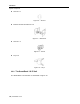

Table Of Contents
- 1 Introduction
- 2 Installation
- 3 Configuring the Network
- 3.1 Boot-Up Process
- 3.2 Logging Onto the Web Configuration Interface
- 3.3 Configuring the Network Settings
- 3.4 Configuring Network SNMP Settings
- 3.5 Configuring User Settings
- 3.6 Configuring the KVM Switch
- 3.7 Configuring the Security Settings
- 3.8 Performing Additional Configuration Operations
- 3.9 Reloading a Page
- 3.10 Saving Changes and Logging Out
- 4 Conducting a Remote Session
- 4.1 Starting a Remote Session
- 4.2 Sharing a Remote Session
- 4.3 Displaying the Toolbar
- 4.4 Setting the Session Profile
- 4.5 Verifying Remote Presence Solutions Information
- 4.6 Changing the Video Performance Settings
- 4.7 Adjusting the Video
- 4.8 Managing Keyboard Sequences
- 4.9 Synchronizing Mouse Pointers
- 4.10 Switching to a Different Server
- 4.11 Disconnecting the Remote Session
- 5 Troubleshooting – Safe Mode
- 6 Operating the SmartRack 116 IP Switching System Locally
- Activating Password Protection
- Changing the OSD Hotkey
- Activating Autoskip
- Serial Port
- Changing the Keyboard Language
- Editing the Switch Name
- Restoring OSD to Factory Defaults (F7)
- 6.3 Upgrading the SmartRack 116 IP Firmware
- 6.3.1 Downloading Update Software and Latest Firmware
- 6.3.2 Update Software System Requirements
- 6.3.3 Connecting the SmartRack 116 IP System
- 6.3.4 Connecting the RS232 Download Cable
- 6.3.5 Installing the Software
- 6.3.6 Starting and Configuring the Update Software
- 6.3.7 Verifying the Version Numbers
- 6.3.8 Obtaining New Firmware
- 6.3.9 Restoring Factory Settings
- 6.4 Troubleshooting – Update Software
- 7 Technical Specifications
- 8 Video Resolution and Refresh Rates
- 9 SNMP Events Table

Installation
Pre-Installation Guidelines
User Guide | 19
Figure 10 – SmartRack 116 IP Switch Ports
The following table describes the functionality of the ports of the SmartRack 116 IP
Switch.
Port Functionality
Serial
Not in use
Flash
For updating firmware of the analogue part of the SmartRack 116 IP Switch system - OSD,
Switch, RICCs, and ROCs.
LAN
For connecting to the 10/100 Mbit Ethernet. The LED illuminates green when the unit is
connected to a 100 Mbit/sec network; it illuminates yellow when the unit is connected to a
10 Mbit/sec network.
Server ports
For connecting to the servers via the
RICC/ROCs.
2.3 Pre-Installation Guidelines
Place cables away from fluorescent lights, air conditioners, and machines that are
likely to generate electrical noise.
Place the SmartRack 116 IP unit on a flat, clean and dry surface.
The SmartRack 116 IP unit is not intended for connection to exposed outdoor
lines.
Ensure that the maximum distance between each computer and the SmartRack
116 IP unit, does not exceed 10 m / 33 ft for RICCs, and 30 m/100 ft for ROCs.
2.4 Rack Mounting SmartRack 116 IP
Mounting SmartRack 116 IP into a rack can be performed by:
1. Replacing the short bracket with a long bracket, if required for greater rack depth