Smart CAT5 Switch 16 IP Operating Guide w w w . m i n i c o m . c o m International HQ North American HQ European HQ Jerusalem, Israel Linden, New Jersey Dübendorf, Switzerland Tel: + 972 2 535 9666 minicom@minicom.com Tel: + 1 908 4862100 info.usa@minicom.com Tel: + 41 1 823 8000 info.europe@minicom.com Customer support - support@minicom.com 5UM20114 V1.
SMART CAT5 SWITCH 16 IP. Table of Contents Welcome........................................................................................................................................ 3 Section 1: The Smart CAT5 Switch 16 IP system .......................................... 4 1. 2. 3. 4. 5. 6. 7. 8. 9. 10. 11. 12. 13. 14. 15. 16. 17. 18. 19. 20. 21. 22. 23. 24. 25. 26. 27. 28. 29. 30. 31. 32. 33. 34. 35. 36. 37. 38. Configuring the IP system ............................................................
OPERATING GUIDE. Section 2: Operating the Smart 16 IP system locally.................................. 56 39. 40. 41. 42. 43. 44. 45. 46. 47. 48. 49. 50. 51. 52. 53. 54. 55. 56. Switching between computers ...................................................................................... 56 The keyboard hotkeys.................................................................................................... 56 The OSD...................................................................................
SMART CAT5 SWITCH 16 IP. Welcome The Smart CAT5 Switch 16 IP system is produced by Minicom Advanced Systems Limited. Technical precautions This equipment generates radio frequency energy and if not installed in accordance with the manufacturer’s instructions, may cause radio frequency interference. This equipment complies with Part 15, Subpart J of the FCC rules for a Class A computing device.
OPERATING GUIDE. S ec t io n 1: T h e S m a r t C A T 5 S w it c h 16 I P s y s t em This section explains how to configure and operate the Smart CAT5 Switch 16 IP (Smart 16 IP) system remotely over IP. When Operating the Smart 16 IP Switching system locally through the On Screen Display (OSD) or Control software see Section 2 page 56. 1. Configuring the IP system The Smart 16 IP's communication interface is based on TCP/IP, and it comes configured with the values listed below.
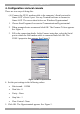
SMART CAT5 SWITCH 16 IP. 4. Configuration via local console There are two ways of doing this: (A) Connect the NULL modem cable to the computer’s Serial port and to Smart 16 IP’s Serial 1 port. Use any Terminal software to connect to Smart 16 IP. The screen shots below use Windows Hyperterminal. 1. Choose Start/Programs/Accessories/Communications/Hyperterminal. 2. When prompted enter a name and click OK. The Connect To box appears. See Figure 1. 3. Fill in the connection details.
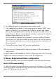
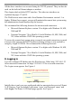
OPERATING GUIDE. Figure 3 The Hyperterminal 6. Press Enter. Some device information and a prompt appear. 7. Type config and press Enter. Configuration questions appear. DHCP can be enabled or disabled. You can change the IP address, net mask and default gateway. Pressing Enter without entering values keeps the default values. To contact Smart 16 IP from outside the LAN configure a gateway. To remove an already configured gateway, type 0.0.0.0.
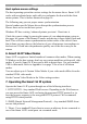
SMART CAT5 SWITCH 16 IP. Host system mouse settings The host operating system has various settings for the mouse driver. Smart 16 IP works with accelerated mice and is able to synchronize the host with the client mouse pointer. This is further discussed on page 14. The following may prevent proper mouse synchronization. Special vendor-specific Mouse drivers disrupt the synchronization process. Ensure these are not on the host system Windows XP has a setting ' enhanced pointer precision’. Deactivate it.
OPERATING GUIDE. All the above interfaces are accessed using the TCP/IP protocol. They can thus be used via the built-in Ethernet adapter or modem. This chapter deals with the HTTP interface. The other two interfaces are explained on pages 37 and 19. The Web browser must come with a Java Runtime Environment version 1.1 or higher. Without Java support, you can still maintain the remote host system using the administration forms displayed by the browser.
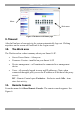
SMART CAT5 SWITCH 16 IP. Menu Work area Figure 5 The Smart 16 IP Home page 9. Timeout After half an hour of non-activity the system automatically logs out. Clicking anywhere on the screen will lead back to the Login screen. 10. The Work area The Work area has a short summary about your Smart 16 IP.
OPERATING GUIDE. Information bar Control buttons Computer buttons Figure 6 The remote console You can work on it with the keyboard and mouse. The delay with keyboard and mouse reactions - if any - depends on the line connection bandwidth. 12. Keyboard layout Your host keyboard changes its layout to match the remote host system. So for example if the host system uses a US English keyboard layout, special keys on a German keyboard won't work but will function as US English keys.
SMART CAT5 SWITCH 16 IP. In case Smart 16 IP is connected to your local network environment and your connection to the Internet is available using a proxy server only without NAT being configured, the Remote Console is very unlikely to be able to establish the according connection. This is because today's Web proxies are not capable of relaying the RFB protocol. In case of problems, please consult your network administrator in order to provide an appropriate network environment.
OPERATING GUIDE. Mouse handling - The submenu for mouse handling offers 3 options for synchronizing the host and the client mouse pointer - explained on pages 14 and 16. The option for 'Fast Sync' shows the hotkey if you defined one using the Remote Console Settings. Local cursor - Choose a cursor shape for the host mouse. The number of available shapes depends on the Java Virtual Machine, only version 1.2 or higher offers the full list.
SMART CAT5 SWITCH 16 IP. Type here Figure 7 Chat window All messages are broadcast to ALL connected users. There is no option to direct a message to a particular user only. There is no message history, so messages can only be received after opening the Remote Console. Type your message and press Enter. To end the Chat, close the Chat window. The Video settings From the Options menu choose Video Settings. The Video Settings box appears. See Figure 8.
OPERATING GUIDE. Phase - Sets the phase for video sampling. Horizontal Offset - Moves the picture in a horizontal direction. Vertical Offset - Moves the picture in a vertical direction. Brightness and contrast affect all modes and KVM ports globally; the other settings are changed specifically for each mode on each KVM port. - Resets mode to factory defaults. - Resets all modes to factory defaults. - Saves changes. - Undoes changes that have not yet been saved.
SMART CAT5 SWITCH 16 IP. Pressing the button usually leads to a fast sync, except when the KVM port or the video mode recently changed. 15. Mouse synchronization limitations Synchronization may not work properly in the following cases: 1. For the intelligent sync to work, the picture MUST be correctly adjusted. Use the auto adjustment function or the manual correction in the Video Settings panel to adjust the picture. The video must also be of sufficiently good quality. 2.
OPERATING GUIDE. Figure 10 Motion tab The Speed section slider bar must be in the center, and the Acceleration section must be set to None. Click OK to save changes. 4. Disable Active Desktop. Or do not use a plain background, use a wallpaper. Disabling mouse acceleration in for other Operating Systems To disable mouse acceleration in for other Operating Systems, see Appendix C on page 82. 16.
SMART CAT5 SWITCH 16 IP. 17. Remote Console Settings From the Smart 16 IP Menu click Remote Console Settings. The Remote Console Settings window appears. See Figure 11. Figure 11 The Remote Console Settings The settings and their functions are now described. All settings are user specific. Choose a user from the Drop-down menu. Transmission Encoding - Optimizes the speed of the remote screen depending on the number of parallel users and the bandwidth of the connection line.
OPERATING GUIDE. Color Depth – The lower the depth the faster the speed. Various Remote Console Options Start in Monitor Mode - Check this option to open the Remote Console window in read only mode. (No keyboard or mouse transferred to Host computer). Exclusive Access- Enables the Exclusive Access mode at Remote Console startup. This forces the Remote Consoles of all other users to close. No one can open the Remote Console until this user disables the Exclusive Access or logs off.
SMART CAT5 SWITCH 16 IP. The * sign inserts a pause with a definable duration. See page 25. To require a confirmation request before keystrokes are sent, write confirm at the start. E.g. confirm Ctrl+Alt+Delete. For a list of key codes and aliases Smart 16 IP recognizes, refer to Appendix B on page 80. Press Apply for the changes to take effect. Home Page Refresh – Refreshes the Smart 16 IP Home page, so that direct Smart IP Links updates their status. 18.
OPERATING GUIDE. quit - Logs out current user and disconnects from the client. version - Shows all available version numbers terminal - Starts the terminal passthrough mode for serial port 1. The key sequence ` exit' switches back to command modus. 19. Status via IPMI The Status via IPMI function shows the current values and the min/maxthresholds of all fans, temperatures and voltages existing in the host system. Change the thresholds by editing the values and pressing Apply.
SMART CAT5 SWITCH 16 IP. Internal power Once connected enable the internal power option using the Serial settings on page 37. The Power Control panel enables access to the most important external buttons of your host system. These buttons are the reset and the ATX power button. The power button represents the ATX power button on your host system. It is used to switch the power supply on and off. The ATX power button has 2 operation modes: a short press, and a press of about 4 seconds.
OPERATING GUIDE. the panel that is loaded into the browser because of the button press. The power state will be off. External power If the external power option is enabled it will look like Figure 13. Figure 13 External power control The upper half is used to switch the power for the KVM port currently active. Use the KVM settings – see page 24 - to assign a port of the external power control to a KVM port. If no assignment exists, the option is disabled.
SMART CAT5 SWITCH 16 IP. Figure 14 Keyboard & Mouse Settings The elements of the Keyboard & Mouse Settings are explained below. Host Interface – Only Auto or PS/2 are active. USB is for future applications. Targeted KVM port 1. Choose a port to which a Host computer is connected. 2. Press to display the current values for the selected KVM port. Without pressing alterations will NOT be made to the chosen port. Keyboard Model - Choose the keyboard model for the chosen port.
OPERATING GUIDE. Fixed Mouse speed When Mouse Acceleration on the Host computer is disabled, select Fixed Mouse Speed see Figure 15. Also in the Scaling drop-down menu select 1.00. Repeat this procedure separately for each Host computer. Figure 15 Mouse settings G&D Equalizer – This supports to the mouse synchronization for Guntermann & Drunck KVM switches.
SMART CAT5 SWITCH 16 IP. Figure 16 KVM Settings The elements of the KVM Settings are explained below. Active Port To switch to a computer: 1. Choose a number in the Active port Drop-down list. 2. Press . The computer screen appears in the Remote Console. Number of Ports To set the number of ports the KVM uses: 1. Choose a number in the Number of Ports Drop-down list. 2. Press . The number of rows chosen appears in the KVM Port Settings list. See Figure 17.
OPERATING GUIDE. Figure 17 KVM Port Settings 25. KVM Port Settings 1. Assign names for each port. 2. Define hotkeys to switch to each port. Choose either Minicom default hotkeys by selecting Minicom KVM-Switch in the Default configuration box, and then click the Set Defaults button. Or choose your own hotkeys. The syntax to define a new hotkey is as follows: [ + | - | * ] . For example LShift-LShift-*1-Enter. A + sign means that the keys are pressed together.
SMART CAT5 SWITCH 16 IP. If an external power option is enabled it is possible to assign a port of this control for power switching to each KVM port, see page 20. Show in console – check this option to have a button with the port name appear on the top of the Remote console. Click the button to switch to that computer. Power Control – Click Assign to configure the power option for each port. The following screen appears. Figure 18 Power option Select the Serial port to which Power switch is connected.
OPERATING GUIDE. Each selection adds the outlet to the list at the bottom. The order of powering off/on, will be the order as set out in this list. Changing the order To change the order the outlets are powered on/off: Highlight the desired outlet and move it using the arrows. 26. Video Settings From the Smart 16 IP Menu choose Video Settings. The Video settings appear. See Figure 19.
SMART CAT5 SWITCH 16 IP. Custom Video Modes Add video modes to Smart 16 IP, which are not recognized using the factory settings, when for example using special model lines in an X-Window configuration on the host or with uncommon hosts or operating systems. Click Add Custom Video Modes. The Custom Video Modes window appears see Figure 20. Note! This option may affect the correct video transmission and is for advanced users only. The maximum number of custom video resolutions is 4.
OPERATING GUIDE. Polarity - The polarity (positive/negative) of the synchronization signals. V means vertical, H means horizontal. Description Give the mode a name. The name appears in the Remote Console when the custom mode is activated. 27. User/Group Management From the Smart 16 IP Menu choose User/Group Management. The User/Group Management settings appear. See Figure 21. The user and group management of Smart 16 IP is based on configurable users and groups.
SMART CAT5 SWITCH 16 IP. Email address /Mobile number These are optional. Group membership/Member of/Not Member of Each user can be a member of one or more groups and inherit the rights of that group. Use the arrows to add or remove a user from a group. Existing groups Select an existing group for copying, modification or deletion. New group name To create a new group, enter a new group name. Create User button Once the required fields are filled in, click the Create User button to create a new user.
OPERATING GUIDE. 2. Enter a new user name in the New user name box. 3. Click the Copy User button. All properties of the selected user will be copied to the new one, except user specific permissions. Group Management The following headings appear under Group Management. Create group button To create a group: 1. Type a name into the New group name box 2. Click the Create group button. Delete Group button To delete a group: 1. Select a group in the Existing groups Drop-down list. 2.
SMART CAT5 SWITCH 16 IP. Figure 22 User/Group Permissions Each user or group has a set of access rights to the Smart 16 IP functions. The user 'super' always has unalterable full access rights. A newly created user has the access rights of all groups he belongs to. You can change the access rights in the User/Group Permissions panel. The panel shows the changes to the access rights inherited by the user's ancestors only.
OPERATING GUIDE. Changing a field setting. Allow change means you can change it. (This doesn’t give an automatic right to view the value, the allow view value must also be set). Deny change means you cannot change it. Using a function. allow access means you can use it. deny access means you cannot use it. 3. Select the desired permission and click Apply. 29. Network Settings From the Smart 16 IP Menu choose Network Settings. The Network Settings appear. See Figure 23.
SMART CAT5 SWITCH 16 IP. gateway address and net mask. Before you connect Smart 16 IP to your local subnet, complete the corresponding configuration of your DHCP server. BOOTP - When selected, Smart 16 IP will contact a BOOTP (Bootstrap Protocol) server in the local sub-net to obtain a valid IP address, gateway address and net mask. IP address Static IP address in the usual dot notation. Subnet mask The net mask of the local network.
OPERATING GUIDE. Telnet port Port number at which Smart 16 IP's Telnet server is listening. If empty the default value is used. Bandwidth limitation The maximum network traffic generated through the Smart 16 IP Ethernet device. Disable Setup Protocol Exclude the Smart 16 IP from the setup protocol. 30. Dynamic DNS Use the free Dynamic DNS service at www.dyndns.org. See Figure 24. Administrator PC Internet DSL Dynamic IP NAT Dynamic DNS server www.dyndns.
SMART CAT5 SWITCH 16 IP. 2. From the Smart 16 IP menu choose Network Settings / Dynamic DNS. The Dynamic DNS Settings appear. See Figure 25. Figure 25 Dynamic DNS Settings 3. Check the Enable Dynamic DNS box. 4. Change the settings as desired. Hostname - The Hostname registered during manual registration with the Dynamic DNS Server. Spaces are not allowed in the Hostname. Username/Password – Fill in the Username and Password.
OPERATING GUIDE. Figure 26 Serial Port Settings In the Smart 16 IP Serial Settings specify the devices connected to the two Serial ports. Serial Port 1 The port options are listed below Configuration login –If this option is checked you can only use the port for the initial configuration and no other function. Modem - Smart 16 IP has the option of remote access using a telephone line. Connect the modem to Serial 1 port.
SMART CAT5 SWITCH 16 IP. Modem Server IP address – This address is used only when connecting to Smart 16 IP via a modem. When you dial into the Smart 16 IP the client computer will receive a Modem Client IP address from the Smart 16 IP. Open the Web browser and type Modem server IP address to login to the Smart 16 IP. The Client IP (see paragraph below) must be in the same class C subnet as the server IP.
OPERATING GUIDE. Serial Port 2 This port provides the power control options, see page 20. Choose a suitable setting and fill in additional required options. Smart 16 IP supports the following: Internal Power Option - This option gives access to the ATX power and reset functions of a single connected system. You can change the duration of each button press. To do so, click Change button press durations. The box below appears. Adjust the time as desired.
SMART CAT5 SWITCH 16 IP. Figure 29 Serial Port 2 external power option IPM 220-L (Inline Power Module) - External module option to switch power of a single system by putting it in the power supply line of the controlled system. SPC 800/1600 - Using the AvocentTM SPC, switch power for more than one system connected to Smart 16 IP through a KVM switch. To use this device enter a username and password, which exist on the SPC and have the privileges to switch power for each port.
OPERATING GUIDE. Figure 30 Security Settings SSL settings Force HTTPS - Access the Web front-end only using an HTTPS connection. Smart 16 IP won't listen on the HTTP port for incoming connections. KVM encryption - Controls the encrypting of the RFB protocol, used by the Remote Console to transmit the screen data to the administrator machine and keyboard and mouse data back to the host. Off - No encrypting used. Try - Tries to make an encrypted connection.
SMART CAT5 SWITCH 16 IP. 1. From the Security Settings page choose Create your own SSL certificate. The window appears as in Figure 31. Figure 31 CSR 2. Fill in the fields: Common name - Network name of Smart 16 IP once installed in the user's network. It is identical to the name that is used to access the card with a Web browser. In case the name given here and the actual network name differ, the browser will pop up a security warning when the card is accessed over HTTPS.
OPERATING GUIDE. Key length - Length of the generated key in bits. 1024 Bits are supposed be sufficient for most cases. Larger keys may result in slower response time during the connection. 3. Click . 4. Press Download CSR to download the CSR to your administration machine. 5. Send the CSR to a CA for certification. They will send a new certificate 6. Press Upload to upload the certificate to Smart 16 IP. The certificate uploads.
SMART CAT5 SWITCH 16 IP. 0.0.0.0/0 matches any IP packet Policy - Determines what to do with matching packets. They are accepted or dropped. NOTE: The order of the rules is important. The rules are checked in ascending order until a rule matches. Rules below the matching one are ignored. The default policy applies if no match has been found. Append a rule – To add a rule to the end of the rule list: Enter the IP/Mask and set the policy. Then press .
OPERATING GUIDE. • Currently active users with login time (login time is only valid if time is synchronized on Smart 16 IP) • Server's power state • The following actions can be initiated via SNMP: • Reset server • Power on/off server • Reset Smart 16 IP The following events are reported by Smart 16 IP via SNMP: • Login trial at Smart 16 IP failed • Login trial at Smart 16 IP succeeded • Denying access to a particular action. • Server was reset.
SMART CAT5 SWITCH 16 IP. Read Community - This is the SNMP community, which allows you to retrieve information via SNMP. Write Community - This community allows you to set options and reset Smart 16 IP or the host via SNMP. System Location - Type a description of the physical location of the host. This will be used in reply to the SNMP request "sysLocation.0". System Contact - Type a contact person for the host. This will be used in reply to the SNMP request "sysContact.0".
OPERATING GUIDE. Both require IPMI V1.5. From the Smart 16 IP Menu choose IPMI Settings. The IPMI Settings appears. See Figure 33. Figure 33 IPMI Settings IPMI disabled - Disables IPMI. Status via IPMI and Event Log via IPMI are not available and the power on/off and reset functions won't use IPMI. BMC address - Hexadecimal Baseboard Management Controller address. Needed for all types of communication to the IPMI-interface. Usually you can find this address in the BIOS of the host system.
SMART CAT5 SWITCH 16 IP. 35. LDAP Settings You can keep authentication information in a central LDAP directory. The purpose of LDAP is simply to confirm the password during login with the LDAP server. The user must exist on both the LDAP and Smart IP 16 side. On login Smart IP 16 internal user management checks the user. If the user is verified the password is then checked against the LDAP server.
OPERATING GUIDE. Name of user-entry object class - The object class that identifies a user in the LDAP directory. To use the default leave this field empty. The default depends on the selected LDAP server type. User search subfilter - Refine the search for users that should be known to the Smart 16 IP. 36. Maintenance From the Smart 16 IP Menu choose Maintenance. The Smart 16 IP Maintenance window appears. Board Summary - This contains information about the Smart 16 IP and its current firmware.
SMART CAT5 SWITCH 16 IP. Direct SmartIP Links You can set up direct links to any Minicom IP hardware over a LAN or WAN. Use the links to directly connect to these IP units without having to remember their IP addresses. You can also see the status of the remote IP units as explained below. All the IP units must have firmware that supports direct connection functionality. Ensure that firmware of all units is updated to the latest version. See the User Guide of each IP unit to update the firmware.
OPERATING GUIDE. 4. In the Device Name column type a description. 5. Click Apply. On the Home page Monitor icons representing the direct connection IP units appear. See Figure 38.
SMART CAT5 SWITCH 16 IP. Direct Connection Links for all Minicom IP Solutions On-Line Status and Direct Links to all Minicom IP products in organization. LAN or WAN CAT5 PHANTOM MX IP Remote Administrator SM A R T GIF A ctivity System OK MINICOM Phantom MX IP Factory RESET SM A R T SWITCH IP GI F MINICOM www.minicom.
OPERATING GUIDE. 37. Frequently Asked Questions Q 1: The remote mouse doesn't work or is not synchronized. A: Ensure the Smart 16 IP mouse settings match the mouse model. Also see page 14 Q 2: Bad video quality or grainy picture A: Use the brightness and contrast settings - see page 13. Use the auto adjustment feature to correct a flickering video. Q 3: Login fails. A: Was the correct user and password given? On delivery, the user "super" has the password "smart".
SMART CAT5 SWITCH 16 IP. 38. Glossary of terms ACPI - A specification that enables the operating system to implement power management and system configuration. ATX - Advanced Technology Extended: A particular specification of a motherboard introduced by Intel in 1995. BMC - Board Management Controller: implements the IPMI based main board management functions. DHCP - Dynamic Host Configuration Protocol: protocol for dynamically assigning IP configurations in local networks.
OPERATING GUIDE. S ec t i o n 2 : O p e r a t i n g t h e S m a r t 1 6 I P s y s t em lo c a l l y This section explains how to operate the Smart 16 IP Switching system locally through the On Screen Display (OSD) or Control software. 39. Switching between computers Switch between the connected computers by either: • Keyboard hotkeys • The OSD (On Screen Display) • Control software The OSD / Control software is also the place to adjust various settings as explained below. 40.
SMART CAT5 SWITCH 16 IP. Figure 40. Lines with blue text show active computers. Lines with grey text show inactive computers. The Type column indicates whether a computer “C” or another switch “S” is connected to the port. C=computer S=switch Port number appears here Instruction keys Figure 40 The OSD Main window 42. Navigating the OSD To navigate up and down use the Up and Down arrow keys. To jump from one column to the next (when relevant) use the Tab key.
OPERATING GUIDE. Figure 41 The Settings window Note! When the OSD is password protected (explained below) only the Administrator has access to the F2 settings window. 45. The General settings With the blue line on the word GENERAL, press Enter. The General settings window appears see Figure 42. Figure 42 The General Settings window From this window you can do the following: Security The OSD comes with an advanced password security system that contains 3 different security levels.
SMART CAT5 SWITCH 16 IP. • Set and modify all Passwords and security profiles • Fully access any computer • Use all OSD functions Supervisor (Status S) The Supervisor can: • Fully access any computer • Access the following OSD functions only –F4 Scan, F5 Tune and F6 Moving the Confirmation label. User (Status U) There are 6 different Users in the Smart 16 IP system. Each User has a Profile set by the Administrator that defines the access level to different computers.
OPERATING GUIDE. 2. Press the Space bar to toggle between options. To display the OSD in future press the new hotkey. Autoskip With the Autoskip feature, the arrow keys only access the active computer lines on the OSD. When Autoskip is Off, The arrow keys access both active and inactive computer lines. To change the Autoskip setting: 1. Navigate to the Autoskip line. 2. Toggle between the options using the Space bar. Serial port The Serial port is used for the Control Management program.
SMART CAT5 SWITCH 16 IP. Figure 43 Ports Settings window Editing the computer name In this window you can edit the computer names with up to 15 characters. To erase a character: Select it and press the Space bar. Blank spaces remain in place of the erased character. To erase an entire line: Place the cursor at the beginning of the line. Keep the Space bar depressed until the line is erased. Keyboard (KB) The Smart 16 IP operates with Windows, Linux, HP UX, Alpha UNIX SGI, DOS, Novell, MAC-USB or Open VMS.
OPERATING GUIDE. Adding/changing a hotkey (HKEY) Cascade the Smart 16 IP by connecting another Smart Switch to a Computer port instead of a computer, and then connecting more RICCs to the second Switch. You must define a different hotkey for the OSD of each Switch. The hotkeys can be any of the choices as set out above on page 59. Use the hotkey when you select the Switch’s port in the first level OSD – the second level’s OSD then appears. To add/change a hotkey: 1.
SMART CAT5 SWITCH 16 IP. 1. On the desired line press Tab to jump to the desired column. 2. Place the cursor over one of the 3 digits and type a new number. Enter a leading zero where necessary. For example, type 040 for 40 seconds. Typing 999 in the LBL column displays the label continuously. Typing 000 – the label will not appear. Typing 999 in the T/O column disables the Timeout function. Typing 000 – the Timeout function works immediately.
OPERATING GUIDE. 50. Security In the Settings window navigate to the Security line and press Enter. The Security settings window appears see Figure 46. Figure 46 The Security settings window The ‘T’ column on the right hand side stands for Type of password. There can only be 1 Administrator password, 1 Supervisor password, and 6 User passwords. To change a user name or password: 1. Navigate to the desired line and column. 2. Type a new user name / password.
SMART CAT5 SWITCH 16 IP. Please note! All the functions set out in the Help window are performed from the Main window. The Help window is merely a reminder of the hotkeys and their functions. 52. Scanning computers – F4 Where necessary adjust the scan time in the Time Settings window, see above. To activate scanning: 1. Press Shift twice to open the OSD. 2. Press F4. Your screen displays each active computer sequentially, with the Scan label appearing in the top left corner.
OPERATING GUIDE. 55. Using the Control software As an alternative to the OSD operate the system with the Control software located on the Marketing & Documentation CD. With the OSD you operate the system and view the computer screens on the same monitor. The Control software requires 2 monitors: 1 for the software and 1 to view the computer screens.
SMART CAT5 SWITCH 16 IP. 4. Double-click the icon to run the software. Or choose Start / Programs / Smart CAT5 RS232 Control / Smart CAT5 RS232 Control. To run the software from the CD: Choose Run Smart CAT5 switch RS232 Control Software from CD. Selecting a Com port During the Setup process you will be prompted to choose a Com port. Choose the Com port to which the RS232 Serial cable is connected. Failure to select the correct Com port will result in the software running in demo mode.
OPERATING GUIDE. Communication Error If a Communication Error box appears when trying to scan the system – see Figure 49. Check that: • The RS232 Serial cable is connected to the computer’s and Smart 16 IP Manager’s serial ports. • The Com Port settings in Options / Com Port are set correctly. After changing the Com port exit and re-enter the Control software. Figure 49 Communication Error The View menu From the View menu choose to display: • All computers, or only active switched on computers.
SMART CAT5 SWITCH 16 IP. computers in system. The system automatically updates the status before every switching. Read Configuration To see the current settings of the entire system (names, scan settings etc.) click . All current settings are received. You view the computer settings from the Control window and other settings from the Edit menu – discussed below. Write Configuration With the Control software you can make changes to all OSD settings.
OPERATING GUIDE. 1. Edit the Logo and Passwords by choosing them from the Edit menu. See figures below. Figure 51 The names and passwords Figure 50 The logo 2. Make the desired changes. 3. Click OK. Settings Choose Settings from the Edit menu. The Computers’ Properties box appears. See Figure 52. Figure 52 The Computers’ Properties box Here you can edit all the data that can be edited in the OSD.
SMART CAT5 SWITCH 16 IP. 3. Check the Select box next to the changed setting. 4. Click OK. Single computer settings To see all the settings of a single computer, right click the computer icon. The settings appear as in the figure below. Note! There is no Select box to check. Figure 53 The single computer Settings box Loading a saved configuration To load a saved configuration: From the File menu choose Open.
OPERATING GUIDE. To change the security access, close and reopen the Control software, and type in the different password. Administrator (Status A) The Administrator can: • Set and modify all Passwords and security profiles • Fully access any computer • Use all functions Supervisor (Status S) The Supervisor can: • Fully access any computer • Scan computers. User (Status U) There are 6 different Users in the Smart 16 IP system.
SMART CAT5 SWITCH 16 IP. The Update software enables you to add new features and fix bugs in a quick and efficient manner. Install the Update software on any computer, even one not part of the Smart 16 IP system. The software and latest firmware is on the Marketing & Documentation CD. To obtain the latest firmware for your system go to www.minicom.com . System requirements for the Update software • Pentium 166 or higher with 16 MB RAM and 10 MB free Hard Drive space. • Free Serial port.
OPERATING GUIDE. Smart Switch RICCs Status box Figure 54 The Smart CAT5 Switch Update window The table below explains the functions of the buttons and boxes in the Update window. Button or Box Function Selects all RICCs Unselects selected RICCs Starts firmware download Displays the firmware version number Displays the hardware version number Cancels selected function System time Displays download status Name of Update file 2. From the Options menu choose Com Port. The Com Port box appears.
SMART CAT5 SWITCH 16 IP. Figure 55 The Com Option box 3. Choose an available Com Port and click OK. Note! The RS232 Serial cable must be connected to the selected Serial port. Verifying the version numbers Before upgrading the firmware, you must first verify which firmware and hardware versions you have. The OSD version number To verify the OSD version number: 1. Open the Smart CAT5 Switch Update program. 2. In the Switch Unit box, check the OSD option. See Figure 54. 3. Click .
OPERATING GUIDE. To verify the RICC version number: 1. Open the Smart CAT5 Switch Update program. 2. Check one or more or all of the RICCs. 3. Click RICC number. . The firmware version number appears after the 4. Click RICC number. . The hardware version number appears after the When “Not responding” appears, there is no computer connected, or it is switched off. Obtaining new firmware Download the latest firmware for your system from www.minicom.
SMART CAT5 SWITCH 16 IP. Figure 56 The Open box 5. Open the file. 6. Click Start. The Smart CAT5 Switch Update flashes the firmware. On completion the firmware version number appears. 7. Check that the updated version number is correct by pressing . Firmware Update generates one log file per session that displays a chronological list of actions. You can read the log file in any ASCII text editor. The log file is located in the Windows directory.
OPERATING GUIDE. Troubleshooting tips When using Firmware Update software you may sometimes get a Communication Error message. When updating a unit and a Communication Error message appears, do the following: 1. Check that the RS232 Serial cable’s RS232 connector is connected to the Switch’s Communication port. 2. Check that the RS232 Serial cable’s DB9F connector is connected to the DB9M Serial port on the CPU’s rear panel. 3. Restart the download process.
SMART CAT5 SWITCH 16 IP. A p p en d ix A : S m a r t 16 I P V id eo m o d es The Smart 16 IP supports the following video modes. Do not use other custom video settings.
OPERATING GUIDE. A p p en d i x B : K e y c o d e s Figure 57 illustrates the keys on a standard 104 key PC keyboard with a US English language mapping. These keys are used to define keystrokes or hotkeys for several Smart 16 IP functions. The keys may not represent keys used on international keyboards. Most modifier keys and other alphanumeric keys are in identical positions, whichever language mapping you are using.
SMART CAT5 SWITCH 16 IP.
OPERATING GUIDE. A p p en d i x C : D i s a b l i n g m o u s e a c c el er a t i o n The following steps describe how to disable mouse acceleration in a number of different Operating Systems. Windows 98 and Windows ME 1. From the Control Panel, click the Mouse icon. 2. From the Mouse Properties dialog box, click the Pointer Options tab. 3. Center the Pointer Speed slider bar 4. Click the Accelerate… button. 5. Deselect Pointer acceleration option. Windows 98 SE and Windows NT4 1.
SMART CAT5 SWITCH 16 IP. Linux 1. Execute the following command line parameter: xset 0 255 2.
OPERATING GUIDE. A p p en d ix D : US B S UN C o m b o k ey s The connected PS/2 keyboard does not have a special SUN keypad to perform special functions in the SUN Operating System environment. So when a RICC USB or SUN is connected to a SUN computer, the RICC emulates these SUN keys using a set of key combinations called Combo keys. See the table below.
SMART CAT5 SWITCH 16 IP. Regional Offices Germany France Italy Kiel Vincennes Rome Tel: + 49 431 668 7933 b.christiansen@minicom.ch Tel: + 33 1 49 57 00 00 info.france@minicom.com Tel: + 39 06 8209 7902 info.italy@minicom.com www.minicom.
OPERATING GUIDE.