Smart IP Extender User Guide International HQ North American HQ European HQ Italy Jerusalem, Israel Linden, New Jersey Dübendorf, Switzerland Rome Tel: + 972 2 535 9666 minicom@minicom.com Tel: + 1 908 4862100 Tel: + 41 1 823 8000 info.usa@minicom.com info.europe@minicom.com www.minicom.com Tel: + 39 06 8209 7902 info.italy@minicom.com Customer support - support@minicom.com 5UM20104 V2.
SMART IP EXTENDER Table of Contents 1. 2. 3. 4. 5. 6. 7. 8. 9. 10. 11. 12. 13. 14. 15. 16. 17. 18. 19. 20. 21. 22. 23. 24. 25. 26. 27. 28. 29. 30. 31. 32. 33. 34. 35. 36. 37. 38. 39. Welcome.......................................................................................................................4 Introduction .................................................................................................................5 Features of IP Extender ...............................................
USER GUIDE 40. 41. 42. 43. 44. 45. 46. 47. 48. 49. 50. 51. 52. 53. 54. 55. 56. 57. 58. 59. 60. 61. 62. 63. 64. 65. 66. 67. 68. 69. 70. 71. 72. 73. 74. 75. 76. 77. 78. 79. 80. 81. Power Control............................................................................................................27 Keyboard & Mouse Settings.....................................................................................28 KVM Settings ..................................................................................
SMART IP EXTENDER 82. 83. Access via Telnet ......................................................................................................57 Telnet server commands ..........................................................................................57 Frequently Asked Questions ................................................................................. 58 Glossary of terms ...................................................................................................
USER GUIDE 1. Welcome The Smart IP Extender system is produced by Minicom Advanced Systems Limited. Technical precautions This equipment generates radio frequency energy and if not installed in accordance with the manufacturer’s instructions, may cause radio frequency interference. This equipment complies with Part 15, Subpart J of the FCC rules for a Class A computing device.
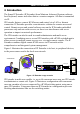
SMART IP EXTENDER 2. Introduction The Smart IP Extender (IP Extender) from Minicom Advanced Systems redirects local keyboard, mouse and video data to a remote computer. All data is transmitted via IP. IP Extender features, remote KVM access and control via a LAN or Internet connection. IP Extender provides a non-intrusive solution for remote access and control.
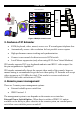
USER GUIDE Smart IP Extenders MINICOM Activity System OK SMART IP Extender MINICOM Activity MINICOM Activity MINICOM Activity System OK SMART IP Extender KVM Matrix switch Administrators System OK SMART IP Extender System OK SMART IP Extender IP Network Figure 2 Multiple users/servers 3. Features of IP Extender • KVM (keyboard, video, mouse) access over IP or analogous telephone line.
SMART IP EXTENDER IPMI Version 1.5 - defines a serial connection to access certain system parameters and perform system actions like powering down or a hard reset. Modern server systems, supporting the IPMI V1.5 specification, provide a mode where the externally available COM2 serial connection can be configured as a system management port (sometimes called an emergency management port). IP Extender may use this port in order to enable remote system management operations. 5.
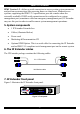
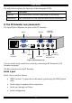
USER GUIDE The table below explains the functions of the front panel LEDs. LED Function Activity LED blinks when Network connection is functioning System OK LED solid when IP Link system connected and functioning 8. The IP Extender rear panel ports The figure below illustrates the ports on the IP Extender. Serial 1 www.minicom.
SMART IP EXTENDER Serial 2 port The Serial 2 port supports the external power option. Ethernet Connects the IP Extender to an Ethernet network. 9. Pre-installation instructions Place cables away from fluorescent lights, air conditioners and other machines that are likely to generate electrical noise. Switch off the computer and disconnect the keyboard monitor and mouse. 10. Connecting the IP Extender to the host computer/KVM switch Connect the host computer / KVM switch to the IP Extender as follows: 1.
USER GUIDE Computer P110 SD 3 in 1 CPU cable www.minicom.com I 0 USER SERIAL 1 COMPUTER Smart IP Extender RST POWER 100-240 VAC 50/60 Hz SERIAL 2 ETHERNET Figure 5 IP Extender connections to a computer KVM switch STATION 2 SERIAL MOUSE POWER P110 KB PS /2 MOUSE SCREEN COMPUTER 5 COMPUTER 6 COMPUTER 7 COMPUTER 8 COMPUTER 1 COMPUTER 2 COMPUTER 3 COMPUTER 4 SD 3 in 1 CPU cable ProLian t DL 360 9.1 - GB 10k ULT RA2 SC SI 9.1 - GB 10k ULT R A2 SC SI ProLian t DL 360 www.minicom.
SMART IP EXTENDER 11. Connecting the Power management options Figure 7 gives an overview of the three Power management options. MINICOM Activity System OK IPMI SMART IP MINICOM Extender KVM IPMI Server Activity System OK SMART IP Extender KVM Server IPMI version 1.5 interface External power Switch box Figure 7 Power management options 12. Connecting the IPMI option IPMI Version 1.
USER GUIDE 13. Connecting the External Reset/Power Option Refer to the Power Switch guide to connect this to one of the serial ports. To date supported options are: • Minicom Power switch • Avocent—SPC 1 800/1600 • Sentry In-Line Power Module 14. Connecting to Ethernet The Ethernet connector on the IP Extender can be used either for a 100 Mbps 100BASE-TX connection or for a 10 Mbps 10BASE-T connection. The adapter adjusts to the appropriate operation mode automatically. 15.
SMART IP EXTENDER 18. Configuring the system The IP Extender's communication interfaces are based on TCP/IP, and it comes configured with the values listed below. • DHCP - active • IP address - 192.168.0.220 • Net mask - 255.255.255.0 • Default Gateway - None If the above values are unsuitable, change the IP configuration. This can be done in a number of ways: 19.
USER GUIDE Figure 8 Connect To box Figure 9 COM 1 Properties box 4. Set the port settings to the following values: • Bits/second - 115200 • Data bits - 8 • Parity - None • Stop bits - 1 • Flow Control - None 5. Click OK. The Hyperterminal appears. See Figure 10.
SMART IP EXTENDER 6. Press Enter. Some device information and a prompt appear. 7. Type config and press Enter. Configuration questions appear. DHCP must be disabled. You can change the IP address, net mask and default gateway. Pressing Enter without entering values keeps the default values. To contact IP Extender from outside the LAN configure a gateway. To remove an already configured gateway, type 0.0.0.0. The last question – enable IP access control – concerns switching IP packet filtering on or off.
USER GUIDE Check the correct setting by moving the mouse of your administration system to the upper left corner of the Remote Console and moving it there slightly forth and back. This will force mouse synchronization in that corner of the screen. Once that is done you may observe the behavior of your client mouse in accordance to the host one. If both mice desynchronize quickly one of the above may be the reason. 22. IP Extender Video Modes IP Extender recognizes a limited number of common video modes.
SMART IP EXTENDER We recommend the following browsers for an unsecured connection: • Microsoft Internet Explorer version 5.0 or higher with Windows 98, ME, 2000 and XP • Netscape Navigator 7.0 or Mozilla 1.0 with Windows 98, ME, 2000, and XP, Linux and other UNIX like operating systems To access the remote host system using a securely encrypted connection you need a browser that supports the HTTPS protocol. Strong security is only assured by using key length of 128 Bit.
USER GUIDE Menu Work area Figure 12 The IP Extender Home page 25. Timeout After half an hour of non-activity the system automatically logs out. Clicking anywhere on the screen will lead back to the Login screen. 26. The Work area The Work area has a short summary about your IP Extender.
SMART IP EXTENDER 27. Remote Console From the menu click Show Remote Console. The remote console appears. See Figure 13. Information bar Control buttons Computer buttons Figure 13 The remote console You can work on it with the keyboard and mouse. The delay with keyboard and mouse reactions - if any - depends on the line connection bandwidth. 28. Keyboard layout Your host keyboard changes its layout to match the remote host system.
USER GUIDE In case IP Extender is connected to your local network environment and your connection to the Internet is available using a proxy server only without NAT being configured, the Remote Console is very unlikely to be able to establish the according connection. This is because today's Web proxies are not capable of relaying the RFB protocol. In case of problems, please consult your network administrator in order to provide an appropriate network environment.
SMART IP EXTENDER Mouse handling - The submenu for mouse handling offers two options for synchronizing the host and the client mouse pointer - explained on page 23. The option for 'Fast Sync' shows the hotkey if you defined one using the Remote Console Settings. Local cursor - Choose a cursor shape for the host mouse. The number of available shapes depends on the Java Virtual Machine, only version 1.2 or higher offers the full list.
USER GUIDE All messages are broadcast to ALL connected users. There is no option to direct a message to a particular user only. There is no message history, so messages can only be received after opening the Remote Console. 31. The Video settings From the Options menu choose Video Settings. The Video Settings box appears. See Figure 15. Figure 15 The Video settings The parameters have the following functions: Brightness - Brightness control. Contrast Red/Green/Blue- RGB contrast control.
SMART IP EXTENDER - Resets mode to factory defaults. - Resets all modes to factory defaults. - Saves changes. - Undoes changes that have not yet been saved. 32. Video Settings access In the User/Group Permissions section on page 36, it explains how to set access levels for all parameters including Video Settings access. A Remote Console user can always change Brightness, Contrast, Black level and picture positions, whatever his Video Settings access rights.
USER GUIDE 4. Active Desktop. Disable it. Or do not use a plain background, use a wallpaper. 35. Single mouse mode The information above applies to the Double Mouse Mode, where remote and host mouse pointers are visible and need to be synchronized. There is also the Single Mouse mode. In this mode only the client mouse pointer is visible. Single Mouse mode needs a Sun Java Virtual Machine 1.3 or later. Select the mode in the Remote console - see Figure 13.
SMART IP EXTENDER Automatic Detection - The encoding and the compression level is determined automatically from the available bandwidth and the current content of the video image. Normal - Best suited for many parallel users in a LAN environment. Compressed - For low bandwidth Modem connections. 1 is the lowest and 9 the highest compression rate. The IP Extender takes time to compress the data.
USER GUIDE Remote Console Button Keys - Button Keys simulate keystrokes on the remote system that cannot be generated locally. For example `Control + Alt + Delete' on Windows and DOS or `Control + Backspace' on Linux. Define a new Button Key as follows: Type the required keys e.g. Ctrl+Alt+Delete. The + sign means that the keys are pressed together. The – sign means the keys are pressed sequentially. The * sign inserts a pause with a definable duration. See page 30.
SMART IP EXTENDER After reading all entries, Smart 16 IP displays them with their time, sensor and description in accordance with the filter settings. You have the choice between several pre-settings (i.e. last day, last week) or an exact declaration of the start and the end date. Once you change the filter settings, click `Update' to update the shown entries. If the Get sensor names box is checked, all sensor IDs are shown with their respective names.
USER GUIDE Power (short press) - A short press on the ATX button is normally caught by the running operating system that tries to initiate a controlled shut down. Do this to switch off the system. If this does not work try the long press button. After pressing, the power state displayed in the administration panel won't immediately reflect the requested change. A controlled shut down of the system may take some minutes.
SMART IP EXTENDER The elements of the Keyboard & Mouse Settings are explained below. Targeted KVM port 1. Choose the port to which a KVM switch is connected. 2. Press to display the current values for the selected KVM port. Without pressing alterations will NOT be made to the chosen port. Keyboard Model - Choose the keyboard model Mouse Model - Choose the mouse model Direct (1:n) mouse mode Use a direct translation of mouse movements between the host and the remote pointer.
USER GUIDE 42. KVM Settings Adjust the settings for the KVM switches connecting the IP Extender to the host computers. From the IP Extender menu choose KVM Settings. The IP Extender KVM settings appear. See Figure 19. Figure 19 KVM Settings The elements of the KVM Settings are explained below. Active Port To switch to a computer: 1. Choose a number in the Active port Drop-down list. 2. Press . The computer screen appears in the Remote Console.
SMART IP EXTENDER Figure 20 KVM Port Settings 43. KVM Port Settings 1. Assign names for each port. 2. Define hotkeys to switch to each port. Choose either Minicom default hotkeys by selecting Minicom KVM-Switch in the Default configuration box, and then click the Set Defaults button. Or choose your own hotkeys. The syntax to define a new hotkey is as follows: [ + | - | * ] . For example LShift-LShift-*1-Enter. A + sign means that the keys are pressed together.
USER GUIDE Show in console – check this option to have a button appear on the top of the Remote console. Click the button to switch to that computer. 44. Video Settings From the IP Extender Menu choose Video Settings. The Video settings appear. See Figure 21 Figure 21 Video Settings 45. Enable local video port This option decides if the video output on the front panel of IP Extender is active and passing through the incoming signal from the host system. 46.
SMART IP EXTENDER Click Add Custom Video Modes. The Custom Video Modes window appears, see Figure 22. Note! This option may affect the correct video transmission and is for advanced users only. The maximum number of custom video resolutions is 4. Figure 22 Custom Video Modes window Custom Modes Handling – switch custom modes off, or use in addition to the standard video resolutions, or use exclusively - Only. With Only you can force a special video mode for IP Extender.
USER GUIDE Description Give the mode a name. The name appears in the Remote Console when the custom mode is activated. 49. User/Group Management From the IP Extender Menu choose User/Group Management. The User/Group Management settings appear. See Figure 23. The user and group management of IP Extender is based on configurable users and groups. Each user or group can have different access capabilities. The IP Extender is factory set with a supervisor user called `super' with the password ‘smart’.
SMART IP EXTENDER 54. Email address /Mobile number These are optional. 55. Group membership/Member of/Not Member of Each user can be a member of one or more groups and inherit the rights of that group. Use the arrows to add or remove a user from a group. 56. Existing groups Select an existing group for copying, modification or deletion. 57. New group name To create a new group, enter a new group name. 58.
USER GUIDE 61. Copy User To copy an existing user’s properties to a new user: 1. Select a user in the Existing user Drop-down list. 2. Enter a new user name in the New user name box. 3. Click the Copy User button. All properties of the selected user will be copied to the new one, except user specific permissions. 62. Group Management The following headings appear under Group Management. 63. Create group button To create a group: 1. Type a name into the New group name box 2.
SMART IP EXTENDER Figure 24 User/Group Permissions Each user or group has a set of access rights to the IP Extender functions. The user 'super' always has unalterable full access rights. A newly created user has the access rights of all groups he belongs to. You can change the access rights in the User/Group Permissions panel. The panel shows the changes to the access rights inherited by the user's ancestors only.
USER GUIDE Using a function. allow access means you can use it. deny access means you cannot use it. Group setting – Use the access rights inherited from the group(s), the user belongs to. 3. Select the desired permission. 4. To add the right, click Add. To remove the right, check the Delete Entry box. 5. Click Apply. 68. Network Settings From the IP Extender Menu choose Network Settings. The Network Settings appear. See Figure 25.
SMART IP EXTENDER IP auto configuration Choose between the 3 options. None – no IP auto configuration. In this case type a static IP address in the appropriate settings below. DHCP - When selected, IP Extender will contact a DHCP (Dynamic Host Configuration Protocol) server in the local sub-net to obtain a valid IP address, gateway address and net mask. Before you connect IP Extender to your local subnet, complete the corresponding configuration of your DHCP server.
USER GUIDE Remote Console & HTTPS port Port number at which IP Extender's Remote Console server and HTTPS server are listening. If empty the default value is used. HTTP port Port number at which IP Extender's HTTP server is listening. If empty the default value is used. Telnet port Port number at which IP Extender's Telnet server is listening. If empty the default value is used. Bandwidth limitation The maximum network traffic generated through the IP Extender Ethernet device.
SMART IP EXTENDER IP Extender is reachable via the IP address of the DSL router, which is dynamically assigned by the provider. Since the administrator doesn't know the IP address assigned by the provider, IP Extender connects to a special dynamic DNS server in regular intervals and registers its IP address there. The administrator can contact this server as well and pick up the same IP address belonging to his card.
USER GUIDE Check interval - Interval for reporting again to the Dynamic DNS server by IP Extender. IP Extender has its own independent real time clock. Ensure the time setting is correct by configuring a timeserver see page 30. IP Extender registers itself to the Dynamic DNS server slightly different from the time configured. To reduce load peaks on the server we add a random time (0-10 min) to the absolute time value. 70.
SMART IP EXTENDER 71. Serial Port Settings From the IP Extender Menu choose Serial Port Settings. The Serial Port Settings appear. See Figure 28. Figure 28 Serial Port Settings In the IP Extender Serial Settings specify the devices connected to the two Serial ports. Serial Port 1 The port options are listed below Configuration login –If this option is checked you can only use the port for the initial configuration and no other function. Modem - Connect a modem to Serial 1 port.
USER GUIDE Modem Client IP address - This address is assigned to your console computer during the PPP handshake. Since it is a point-to-point IP connection virtually every IP address is possible but ensure, it is not interfering with the IP settings of IP Extender and your console computer. The default value will work in most cases. IPMI over Serial - Check to use this serial port for IPMI 1.5 over serial. See page 51 for more information.
SMART IP EXTENDER Intelligent Power Module - External module option to switch power of a single system by putting it in the power supply line of the controlled system. ePowerSwitch 4 port- Using this switch, switch power for more than one system connected to IP Extender through a KVM switch. ePowerSwitch-Slave – This switch is cascadable to up to 4 power sockets with 8 ports. IP Extender must be connected to the first socket of the cascade via a serial connection. Spectrum Control Inc. - Smart Start Jr.
USER GUIDE Force - Tries to make an encrypted connection. SSL Certificate Management IP Extender uses the SSL (Secure Socket Layer) protocol for any encrypted network traffic between itself and a connected client. When connecting, IP Extender reveals its identity to a client using a cryptographic certificate. This is the same for all IP Extenders and won't match the network configurations applied to the card by its user. The certificate's underlying secret key is also used for securing the SSL handshake.
SMART IP EXTENDER Challenge Password/Confirm- Some certification authorities require a challenge password to authorize later changes on the certificate. The minimum is 4 characters. Email - Of a security contact person that is responsible for IP Extender. Key length - Length of the generated key in bits. 1024 Bits are supposed be sufficient for most cases. Larger keys may result in slower response time during the connection. 3. Click . 4.
USER GUIDE Numbers attached to an IP address with a `/' is the number of valid bits that are used for the given IP address. Examples: 192.168.0.22 or 192.168.0.22/32 matches the IP Address 192.168.0.22 192.168.0.0/24 matches all IP packets with source addresses from 192.168.0.0 to 192.168.0.255 0.0.0.0/0 matches any IP packet Policy - Determines what to do with matching packets. They are accepted or dropped. NOTE: The order of the rules is important.
SMART IP EXTENDER 73.
USER GUIDE Figure 32 SNMP settings You can change the following parameters: Enable SNMP Agent - When checked, IP Extender will answer to SNMP requests. If a community is blank, you cannot perform the request. E.g. if you want to disable the possibility to reset IP Extender via SNMP, don't set a write community. Read Community - This is the SNMP community, which allows you to retrieve information via SNMP.
SMART IP EXTENDER Trap destinations Enter IP addresses, to which the traps will be sent. For every IP address, set an according community so that your management client can identify the SNMP traps. After making the entries click 74. . The IP Extender SNMP MIB Click the link to access the IP Extender SNMP MIB file. With it, an SNMP client can communicate with IP Extender. 75.
USER GUIDE IPMI over Serial - If your host system supports IPMI V1.5 and has an Intel EMP (Emergency Management Port, usually COM2) connector, you can connect IPMI through serial port 1 on IP Extender. Please note: • Set the EMP port to Always enable and switch off the Restricted Mode. • The BMC should accept a null username and a non-null password account as login. • Passwords are 4 -16 characters long.
SMART IP EXTENDER Type of external LDAP Server - Set the type of the external LDAP server. This is necessary since some server types require special handling. Also the default values for the LDAP schema are set appropriately. Choose between Generic LDAP Server, Novell Directory Service and Microsoft Active Directory. If you don’t have Novell Directory Service or Microsoft Active Directory then choose Generic LDAP Server and edit the LDAP schema used (see below).
USER GUIDE After a smooth upload the Update Firmware panel appears showing the current firmware version number and the uploaded firmware version number. 4. Press the Update button. The firmware updates. Warning! This process is irreversible; ensure the IP Extender's power supply won't be interrupted during the update process, as this may cause damage. 5. When prompted reset IP Extender manually by pressing the button. When pressed all connections to the administration or Remote console close.
SMART IP EXTENDER Figure 37 The Direct Connections Links page 3. In the IP address column, type IP addresses of the other Minicom IP units. For up to 16 entries press . 4. In the Device Name column type a description. 5. Click Apply. On the Home page Monitor icons representing the direct connection IP units appear. See Figure 38.
USER GUIDE Note! If the state of one device changes, there may be a delay of some seconds until icon colors reflect the true situation especially where the network link of this device is going down. To connect to an IP unit: Click the desired icon on the Home page. The Login page of that IP unit appears. Figure 39 below illustrates a direct connections link scenario. Direct Connection Links for all Minicom IP Solutions On-Line Status and Direct Links to all Minicom IP products in organization.
SMART IP EXTENDER 82. Access via Telnet Connect via a standard Telnet client using IP Extender’s Telnet server. Use it for passthrough access to a device connected to serial port 1. Connect any serial device, which offers terminal access via its serial port and access it using the Telnet interface. Set the serial settings - see page 42 - according to the requirements of the device. Connect to IP Extender in the usual way required by the Telnet client, e.g. in a UNIX shell: telnet 192.168.0.
USER GUIDE F r e q u en t l y A s k e d Q u e s t io n s Q 1: The client mouse doesn't work or is not synchronized. A: Ensure the IP Extender mouse settings match the mouse model. Also see page 23 Q 2: Bad video quality or grainy picture A: Use the brightness and contrast settings - see page 22. Use the auto adjustment feature to correct a flickering video. Q 3: Login fails. A: Was the correct user and password given? On delivery, the user "super" has the password "smart".
SMART IP EXTENDER G l o s s a r y o f t er m s ACPI - A specification that enables the operating system to implement power management and system configuration. ATX - Advanced Technology Extended: A particular specification of a motherboard introduced by Intel in 1995. BMC - Board Management Controller: implements the IPMI based main board management functions. DHCP - Dynamic Host Configuration Protocol: protocol for dynamically assigning IP configurations in local networks.
USER GUIDE A p p en d ix A : IP E x t en d er V id eo m o d es The IP Extender supports the following video modes. Do not use other custom video settings.
SMART IP EXTENDER A p p en d i x B : K e y c o d e s Figure 40 illustrates the keys on a standard 104 key PC keyboard with a US English language mapping. These keys are used to define keystrokes or hotkeys for several IP Extender functions. The keys may not represent keys used on international keyboards. Most modifier keys and other alphanumeric keys are in identical positions, whichever language mapping you are using.
USER GUIDE Key Psc Scrl Brk Ins Pos1 Pup Del Pdn Key code PRINTSCREEN SCROLL_LOCK BREAK INSERT HOME PAGE_UP DELETE PAGE_DOWN UP LEFT DOWN RIGHT The numerical keypad codes Key Key code num NUM_LOCK 0 NUMPAD0 1 NUMPAD1 2 NUMPAD2 3 NUMPAD3 4 NUMPAD4 5 NUMPAD5 6 NUMPAD6 7 NUMPAD7 8 NUMPAD8 9 NUMPAD9 + NUMPADPLUS / NUMPAD/ * NUMPADMUL NUMPADMINUS CR NUMPADENTER 62 Alternative Alternative NUMPAD_PLUS NUMPAD_MUL NUMPAD_MINUS
SMART IP EXTENDER A p p en d i x C : P i n a s s ig n m e n t s VGA HD-15 5 4 10 3 9 2 8 1 7 6 15 14 13 12 11 Pin 1 2 3 4 5 6 7 8 Assignment Red Green Blue Not connected GND GND red GND green GND blue Pin 9 10 11 12 13 14 15 Assignment 5V GND sync Not connected SDA, DCC, ...
USER GUIDE Serial SUB-D 9 Connector 1 1 2 6 Pin 1 2 3 4 5 3 7 4 8 5 9 Assignment DCD RX TX DTR GND Pin 6 7 8 9 Assignment DSR RTS CTS RI Serial SUB-D 9 Connector 2 1 2 6 3 7 4 8 5 9 Pin Assignment Pin Assignment 1 2 3 4 5 DCD RX TX DTR, Reset1 GND 6 7 8 9 DSR, Reset2 RTS, Power1 DTS, Power2 Not connected Pins 1 and 6 are bridged 64
SMART IP EXTENDER A p p en d i x D : T e c h n ic a l s p e c i f i c a t i o n s Host computer Operating systems Novel, Linux, Windows 98, ME, 2000, XP and later Client computer Operating systems Windows 98, ME, 2000, XP and later, Linux. Internet browser with full Java support Host computer resolution Up to 1600x1200 @60Hz Client computer resolution Recommended resolution should be higher than host computer resolution Host mouse driver Microsoft Driver or Operating System default mouse driver.
USER GUIDE 66
SMART IP EXTENDER 67