
User guide

USER GUIDE
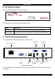
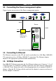
6. IP Link front panel
Figure 2 illustrates the IP Link front panel.
MINICOM
SMART
IP Link
Activity
System OK
Figure 2 Front panel
The table below explains the front panel LEDs.
LED Function
Activity LED blinks when Network connection is functioning
System OK LED solid when IP Link system connected and functioning
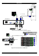
7. The IP Link rear panel ports
The figure below illustrates the ports on the IP Link.
Video In
port
Power connector
Mouse
In port
Keyboard
Out port
Mouse
Out port
Keyboard
In port
Serial
port
Video Out
port
Ethernet
port
www.minicom.com
ETHERNETSERIAL
POWER
100-250 VAC 50/60 Hz
RST
USER COMPUTER
Figure 3 IP Link ports
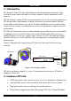
You can work locally on the host system by connecting a KVM console to IP Link
rear panel.
6