Smart IP Link User Guide Supported by: ® Rackit ® Technology Corporation 274 Madison Avenue, New York, NY 10016 Tel: (212) 679-0050 • Fax: (212) 679-0040 Technology Corporation 1 . 8 0 0 . 6 3 6 . 3 4 3 4 International HQ North American HQ European HQ Italy Jerusalem, Israel Linden, New Jersey Zurich, Switzerland Rome Tel: + 972 2 535 9666 minicom@minicom.com Tel: + 41 1 455 6220 Tel: + 1 908 4862100 info.usa@minicom.com info.german@minicom.com www.minicom.com Tel: + 39 06 8209 7902 info.
SMART IP LINK Welcome The Smart IP Link system is produced by Minicom Advanced Systems Limited. Technical precautions This equipment generates radio frequency energy and if not installed in accordance with the manufacturer’s instructions, may cause radio frequency interference. This equipment complies with Part 15, Subpart J of the FCC rules for a Class A computing device.
USER GUIDE Table of Contents 1. 2. 3. 4. 5. 6. 7. 8. 9. 10. 11. 12. 13. 14. 15. 16. 17. 18. 19. 20. 21. 22. 23. 24. 25. 26. 27. 28. 29. 30. 31. 32. 33. 34. 35. 36. 37. 38. 39. 40. 41. 42. Introduction ................................................................................................................................... 4 Features of IP Link ........................................................................................................................ 4 Remote power management ........
SMART IP LINK Appendix A: IP Link Video modes ........................................................................ 35 Appendix B: Key codes.......................................................................................... 36 Appendix C: Pin assignments ............................................................................... 38 Appendix D: Technical specifications ..................................................................
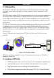
USER GUIDE 1. Introduction The Smart IP Link (IP Link) from Minicom Advanced Systems redirects a host keyboard, mouse and video data to a client computer. Data is transmitted via IP protocol. IP Link features, remote KVM access and control via a LAN or Internet connection. IP Link provides a non-intrusive solution for remote access and control.
SMART IP LINK IP Link supports PS/2 type keyboards and mice and HD 15 video output. See the pin assignments in Appendix C. IP Link automatically detects the current video mode of the console, however manual tuning is recommended to get the best video quality. IP Link will accept video streams up to 110 MHz dot clock. This results in a screen resolution of 1280x1024 dots with a refresh rate of 75 Hz. 3.
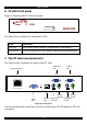
USER GUIDE 6. IP Link front panel Figure 2 illustrates the IP Link front panel. SMART IP Link Activity MINICOM System OK Figure 2 Front panel The table below explains the front panel LEDs. LED Function Activity LED blinks when Network connection is functioning System OK LED solid when IP Link system connected and functioning 7. The IP Link rear panel ports The figure below illustrates the ports on the IP Link. Video Out port www.minicom.
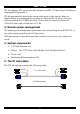
SMART IP LINK Reset button The Reset button resets the IP Link. Serial port The Serial port is used as follows: • Serial pass-through via Telnet • Serial output for external modem dial-in connection • Initial configuration • External power option Ethernet port Connects the IP Link to an Ethernet network. 8. Pre-installation instructions Place cables away from fluorescent lights, air conditioners and other machines that are likely to generate electrical noise.
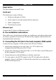
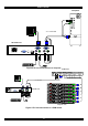
USER GUIDE Computer P110 SD 3 in 1 CPU cable www.minicom.com Smart IP Link USER COMPUTER RST POWER 100-250 VAC 50/60 Hz SERIAL ETHERNET Figure 4 IP Link connections to a computer KVM switch SERIAL MOUSE POWER P110 KB STATION 2 PS/2 MOUSE SCREEN COMPUTER 5 COMPUTER 6 COMPUTER 7 COMPUTER 8 COMPUTER 1 COMPUTER 2 COMPUTER 3 COMPUTER 4 SD 3 in 1 CPU cable ProLi ant DL 360 9.1 - GB 10k ULTRA2 SCSI 9.1 - GB 10k ULTRA2 S CS I www.minicom.com ProLi ant DL 360 9.
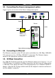
SMART IP LINK 10. Connecting the Power management option www.minicom.com Figure 6 gives an overview of the Power management option. USER COMPUTER RST POWER 100-250 VAC 50/60 Hz SERIAL ETHERNET Serial Server KVM Mains Mouse Keybd External power Switch IPM 220-L Inline Power module, or 3rd party unit 100T Parallel Serial A Video Serial B Figure 6 Power management option 11.
USER GUIDE 13. 100 Mbps Connection For 100BASE-TX Fast Ethernet networks, the IP Link supports Category 5 UTP cabling. To establish a 100 Mbps connection, the cable must be connected to a 100BASE-TX hub. 1. Make sure that the cable is wired appropriately for a standard 100BASE-TX adapter. 2. Align the RJ-45 plug with the notch on the adapter's connector and insert it into the adapter's connector.
SMART IP LINK 17. Configuring system via local console There are two ways of doing this: (A) Connect the NULL modem cable to the computer and to IP Link’s Serial port. Use any Terminal software to connect to IP Link. The screen shots below use Windows Hyperterminal. 1. Choose Start/Programs/Accessories/Communications/Hyperterminal. 2. When prompted enter a name and click OK. The Connect To box appears. See Figure 7. 3. Fill in the connection details. Select COM 1 in the Connect using box and click OK.
USER GUIDE Figure 9 The Hyperterminal 6. Press Enter. Some device information and a prompt appear. 7. Type config and press Enter. Configuration questions appear. DHCP must be disabled. You can change the IP address, net mask and default gateway. Pressing Enter without entering values keeps the default values. To contact IP Link from outside the LAN configure a gateway. To remove an already configured gateway, type 0.0.0.0. Enable IP access control – concerns switching IP packet filtering on or off.
SMART IP LINK 2. Telnet - Use a standard Telnet client to access an arbitrary device connected to the IP Link's Serial port via a terminal mode. All the above interfaces are accessed using the TCP/IP protocol. They can thus be used via the built-in Ethernet adapter or modem. The Web browser must come with a Java Runtime Environment version 1.1 or higher.
USER GUIDE Toolbar buttons Preview screen Figure 11 The IP Link Home page 21. Server Power Status The power status of the server only appears if there is an Inline Power Module (IPM 220-L) attached and is configured in the Serial Settings. See section 38. 22. Timeout After half an hour of non-activity the system automatically logs out. Clicking anywhere on the screen will lead back to the Login screen. 23. Remote Console Click the preview screen or Click to open. The remote console appears.
SMART IP LINK 24. Keyboard layout Your client keyboard changes its layout to match the host system. So for example if the host system uses a US English keyboard layout, special keys on a German keyboard won't work but will function as US English keys. To solve this problem, adjust the client system keyboard to the same mapping as the host one. Alternatively, use the Soft-Keyboard that is part of the Remote Console applet.
USER GUIDE - Single/Double mouse mode - Discussed on page 18. The Options menu Click the Options button to get the following menu: Scaling - Scale down the Remote Console. Not all display details will be preserved. Mouse handling - The submenu for mouse handling offers two options for synchronizing the client and the host mouse pointer - explained on page 18. The option for 'Fast Sync' shows the hotkey if you defined one using the Remote Console Settings.
SMART IP LINK Figure 13 The Video settings The parameters have the following functions: Brightness - Brightness control. Contrast Red/Green/Blue- RGB contrast control. Black level - Sets the intensity of the color black. Clock - Sets the horizontal frequency for a video line, this depends on the video mode. Different video cards may require different values. The default settings and auto adjustment procedure should be adequate for all common configurations.
USER GUIDE • Active Desktop. Disable it. Or do not use a plain background use Wallpaper. Check the synchronization by putting the client mouse cursor into the upper left corner of the Remote Console and move it slightly back and forth. Observe the behavior of the host mouse in accordance to the client one. If the mice desynchronize quickly one of the above may be the reason. 28.
SMART IP LINK 30. Remote Console Settings From the IP Link Home page click window appears. See Figure 14. . The Remote Console Settings Figure 14 The Remote Console Settings The settings and their functions are now explained. All settings are user specific. NOTE! For any of the changes below to take effect, click the page. at the bottom of 31. SSL settings Force HTTPS - Access the Web front-end only using an HTTPS connection. IP Link won't listen on the HTTP port for incoming connections.
USER GUIDE SSL Certificate Management IP Link uses the SSL (Secure Socket Layer) protocol for any encrypted network traffic between itself and a connected client. When connecting, IP Link reveals its identity to a client using a cryptographic certificate. This is the same for all IP Links and won't match the network configurations applied to the IP Link by its user. The certificate's underlying secret key is also used for securing the SSL handshake.
SMART IP LINK Country - Use the 2 letter ISO code, e.g. US for USA, DE for Germany. Email - Of a security contact person that is responsible for IP Link. Challenge Password/Confirm- Some certification authorities require a challenge password to authorize later changes on the certificate. The minimum is 4 characters. Key length - Length of the generated key in bits. 1024 Bits are supposed be sufficient for most cases. Larger keys may result in slower response time during the connection. 3. Click . 4.
USER GUIDE The JVM provides a stable and identical Java Virtual Machine across different platforms. The Remote Console software is optimized for this JVM version and offers wider range of functionality when run in SUN's JVM. Tip! The software is on the Marketing & Documentation CD. So, if you have a slow Internet connection, pre-install the JVM on your administration machine. 34. Mouse hotkey Used for fast mouse synchronization in double mouse mode and to free the grabbed mouse in single mouse mode.
SMART IP LINK 36. Network Settings From the IP Link Home page click window appears. See Figure 16. . The Network Settings Figure 16 Network Settings window The settings and their functions are now explained. The initial IP configuration is usually done directly at the host system. However you can also connect to the IP Link using its pre-configured IP settings. Warning! Changing the network settings of IP Link may result in losing the connection.
USER GUIDE BOOTP - When selected, IP Link will contact a BOOTP (Bootstrap Protocol) server in the local sub-net to obtain a valid IP address, gateway address and net mask. IP address Static IP address in the usual dot notation. Subnet mask The net mask of the local network. Gateway IP address In case the IP Link should be accessible from networks other than the local one, this IP address must be set to the local network router's IP address.
SMART IP LINK Bandwidth limit The maximum network traffic allowed through the IP Link Ethernet device. 37. Dynamic DNS Minicom provides a Dynamic DNS service. See Figure 17. Administrator PC Internet DSL Dynamic IP NAT Dynamic DNS server www.dyndns.minicom.com DSL router LAN IP Link Server Figure 17 Dynamic DNS scenario IP Link is reachable via the IP address of the DSL router, which is dynamically assigned by the provider.
USER GUIDE Figure 18 Dynamic DNS Settings 3. Check the Enable Dynamic DNS box. 4. Change the settings as desired. Dynamic DNS server - Enter the server name where IP Link registers itself in regular intervals. If left blank the default will be used. Nickname - The nickname registered during manual registration with the Dynamic DNS Server. Spaces are not allowed in the Nickname. Check time - IP Link registers itself in the Dynamic DNS server at this time.
SMART IP LINK Figure 19 Serial Port window NOTE! For any of the changes below to take effect, click the page. at the bottom of Passthrough access to serial port via Telnet Connect an arbitrary device to the serial port and access it (assuming it provides terminal support) via telnet. Select the appropriate options for the serial port and use the Telnet Console or a standard telnet client to connect to IP Link.
USER GUIDE Figure 20 Telnet Console Connect to IP Link in the usual way required by the Telnet client, e.g. in a UNIX shell: telnet 192.168.0.220 – (The IP address has been replaced by the one that is actually assigned to IP Link). Type a username and password when prompted. These are identical to those of the Web interface. The user management of the Telnet interface is controlled just like the Web interface. Once logged in, the command line appears to type management commands.
SMART IP LINK Init String - Initialization string. The default value works with all modern standard modems connected to a telephone line. For special modems or if connected to a local telephone switch that requires a special dial sequence to connect to the public telephone network, change this setting by giving a new string. See the modem's manual about the AT command syntax. Server IP address – This address is used only when connecting to IP Link via a modem.
USER GUIDE 39. User settings There are 2 different types of access to the system: • Administrator access • User access An Administrator has unrestricted access to all windows and settings. A User can only access the Remote console and the Telnet console. Each status has its own name and password. Both the name and password can be altered by an Administrator. . The User Management From the IP Link Home page click window appears. See Figure 21.
SMART IP LINK 40. Maintenance From the IP Link Home page click appears. See Figure 22. . The Maintenance window Figure 22 Maintenance window Board Summary This contains information about the IP Link and its current firmware. Maintenance features You can receive firmware updates by email or download them from the Minicom Web site. Save the firmware file on the client computer. To update the firmware: 1. Click Update Firmware. The Update Firmware window appears. See Figure 23.
USER GUIDE 2. Ensure that the host computer/KVM switch is connected to IP Link and switched on during the firmware update. 3. Locate and upload the file from the client computer to IP Link. In case of any errors the upload will be aborted. After a smooth upload the Update Firmware panel appears showing the currently firmware version number and the uploaded firmware version number. 4. Press . The firmware uploads.
SMART IP LINK 41. Frequently Asked Questions Q 1: The host mouse doesn't work or is not synchronized. A: Ensure the IP Link mouse settings match the mouse model. Also see page 18 Q 2: Bad video quality or grainy picture A: Use the brightness and contrast settings - see page 16. Use the auto adjustment feature to correct a flickering video. Q 3: Login fails. A: Was the correct user and password given? On delivery, the user "super" has the password "smart". Configure your browser to accept cookies.
USER GUIDE 42. Glossary of terms DHCP - Dynamic Host Configuration Protocol: protocol for dynamically assigning IP configurations in local networks. DNS - Domain Name System: protocol used to locate computers on the Internet by their name. HTTP - Hypertext Transfer Protocol: the protocol used between web browsers and servers. HTTPS - Hyper Text Transfer Protocol Secure: secure version of HTTP. SSL - Secure Socket Layer: encryption technology for the Internet used to provide secured data transmissions.
SMART IP LINK Appendix A: IP Link Video modes The IP Link supports the following video modes. Do not use other custom video settings.
USER GUIDE Appendix B: Key codes Figure 24 illustrates the keys on a standard 104 key PC keyboard with a US English language mapping. These keys are used to define keystrokes or hotkeys for several IP Link functions. The keys may not represent keys used on international keyboards. Most modifier keys and other alphanumeric keys are in identical positions, whichever language mapping you are using.
SMART IP LINK Key Esc Psc Scrl Brk Ins Pos1 Pup Del Pdn Key code ESCAPE PRINTSCREEN SCROLL_LOCK BREAK INSERT HOME PAGE_UP DELETE PAGE_DOWN UP LEFT DOWN RIGHT The numerical keypad codes Key Key code num NUM_LOCK 0 NUMPAD0 1 NUMPAD1 2 NUMPAD2 3 NUMPAD3 4 NUMPAD4 5 NUMPAD5 6 NUMPAD6 7 NUMPAD7 8 NUMPAD8 9 NUMPAD9 + NUMPADPLUS / NUMPAD/ * NUMPADMUL NUMPADMINUS CR NUMPADENTER 37 Alternative ESC Alternative NUMPAD_PLUS NUMPAD_MUL NUMPAD_MINUS
USER GUIDE Appendix C: Pin assignments VGA HD-15 5 4 10 3 9 2 8 1 7 6 15 14 13 12 11 Pin 1 2 3 4 5 6 7 8 Assignment Red Green Blue Not connected GND GND red GND green GND blue Pin 9 10 11 12 13 14 15 Assignment 5V GND sync Not connected SDA, DCC, ...
SMART IP LINK Serial SUB-D 9 Connector 1 2 6 Pin 1 2 3 4 5 3 7 4 8 Assignment DCD RX TX DTR GND 5 9 Pin 6 7 8 9 39 Assignment DSR RTS CTS RI
USER GUIDE Appendix D: Technical specifications Host computer Operating systems Windows 3.1, 9x, 2000, XP, NT4, 2003 Server, DOS, Novel 3.12-6, Linux Client computer Operating systems Windows 98, 2000, XP and later, Linux, MAC 10x. Internet browser with full Java support Max. host computer resolution Up to 1280x1024 @75Hz Client computer resolution Recommended resolution should be higher than host computer resolution Host mouse driver Microsoft Driver or Operating System default mouse driver.
SMART IP LINK 41
USER GUIDE 42