
Installation guide
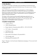


SMART CAT5 SWITCH 16 IP
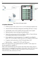
5. Smart 16 IP front panel
Figure 2 illustrates the Smart 16 IP front panel.
www.minicom.com
SWITCH IP
MINICOM
CAT5
SMART
Activity
System OK
Figure 2 Front panel
The Reset button resets the Smart 16 IP.
The table below explains the functions of the front panel LEDs.
LED Function
Activity LED blinks when Network connection is functioning
System OK LED solid when IP Link system connected and functioning
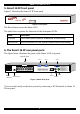
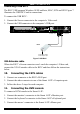
6. The Smart 16 IP rear panel ports
The figure below illustrates the ports on the Smart 16 IP rear panel.
Power
connector
Service port
Computer ports
POWER
85-265 VAC 50/60 Hz
12345678
10 11 12 13 14 15 169
COMPUTER
www.minicom.com
RST
Ethernet
ETHERNET
Keyboard
Mouse
Montor
USER
Serial 1
SERIAL 1
Serial 2
SERIAL 2
SERVICE
Figure 3 Smart 16 IP ports
You can work locally on the host system by connecting a KVM console to Smart 16
IP rear panel.
5.