Smart CAT5 Switch 16 IP Installation Guide International HQ North American HQ European HQ Italy Jerusalem, Israel Linden, New Jersey Dübendorf, Switzerland Rome Tel: + 972 2 535 9666 minicom@minicom.com Tel: + 41 1 823 8000 Tel: + 1 908 4862100 info.usa@minicom.com info.europe@minicom.com www.minicom.com Tel: + 39 06 8209 7902 info.italy@minicom.com Customer support - support@minicom.com 5UM20112 V1.
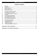
SMART CAT5 SWITCH 16 IP Table of Contents 1. 2. 3. 4. 5. 6. 7. 8. 9. 10. 11. 12. 13. 14. 15. 16. 17. 18. Welcome......................................................................................................................................... 2 Introduction ................................................................................................................................... 3 System components .............................................................................................
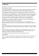
I INSTALLATION GUIDE 1. Welcome The Smart CAT5 16 IP system is produced by Minicom Advanced Systems Limited. Technical precautions This equipment generates radio frequency energy and if not installed in accordance with the manufacturer’s instructions, may cause radio frequency interference. This equipment complies with Part 15, Subpart J of the FCC rules for a Class A computing device.
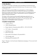
SMART CAT5 SWITCH 16 IP 2. Introduction The Smart CAT5 Switch 16 IP (Smart 16 IP) from Minicom Advanced Systems redirects local keyboard, mouse and video data to up to 16 remote servers. All data is transmitted via IP. Smart 16 IP features remote KVM access and control via a LAN or Internet connection. It provides a non-intrusive solution for remote access and control.
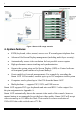
I INSTALLATION GUIDE Figure 1 Smart 16 IP usage scenario 4. System features • KVM (keyboard, video, mouse) access over IP or analogous telephone line.
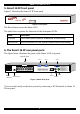
SMART CAT5 SWITCH 16 IP 5. Smart 16 IP front panel Figure 2 illustrates the Smart 16 IP front panel. CAT5 SMART SWITCH IP MINICOM Activity System OK www.minicom.com Figure 2 Front panel The Reset button resets the Smart 16 IP. The table below explains the functions of the front panel LEDs. LED Function Activity LED blinks when Network connection is functioning System OK LED solid when IP Link system connected and functioning 6.
I INSTALLATION GUIDE Serial 1 port Serial 1 port is used as follows: • IPMI Version 1.5 connection to the remote system using the IPMI Option cable • Serial output for modem dial in connection • Serial pass-through via Telnet • Initial configuration Serial 2 port The Serial 2 port supports the internal and external power options Ethernet Connects the Smart 16 IP to an Ethernet network. 7.
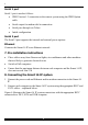
SMART CAT5 SWITCH 16 IP Figure 4 Smart 16 IP system connections 9. The RICCs The RICCs draw their power from the computer’s keyboard port (RICC PS/2, SUN) or from the USB port (RICC USB). Connecting a PS/2 RICC Figure 5 illustrates the RICC. To connect the PS/2 RICC: 1. Connect the Screen connector to the computer’s Video card. 2. Connect the Keyboard connector to the computer’s Keyboard port. 3. Connect the Mouse connector to the computer’s Mouse port. 7.
I INSTALLATION GUIDE NetServer tc2100 To computer’s keyboard port Keybd Mouse 100T To computer’s mouse port Parallel Serial A RICC Video Serial B To computer’s Video card SCSI CAT5 cable to Smart CAT5 Computer port PCI 33Mx32b PCI 33Mx32b PCI 33Mx32b PCI 33Mx32b Figure 5 PS/2 RICC Connecting a SUN RICC Figure 6 illustrates the SUN RICC and its connections. To connect the SUN RICC: 1. Connect the Screen connector to the computer’s Video card. 2.
SMART CAT5 SWITCH 16 IP Connecting a USB RICC The RICC USB supports Windows 98 SE and later, MAC, SUN and SGI. Figure 7 illustrates the USB RICC and its connections. To connect the USB RICC: 1. Connect the Screen connector to the computer’s Video card. 2. Connect the USB connector to the computer’s USB port.
I INSTALLATION GUIDE 12. Connecting the power supply Connect the Smart 16 IP to the power supply using the Power cable provided. 13. Rack mounting the Smart 16 IP Use the plate and screws provided to mount the Smart 16 IP on a server rack as illustrated below. CAT5 SMART SWITCH IP MINICOM Activity System OK www.minicom.com Insert screws to connect to Switch side panel Insert screws to connect to rack 14.
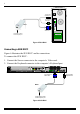
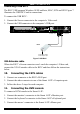
SMART CAT5 SWITCH 16 IP 15. Connecting to Ethernet The Ethernet connector on the Smart 16 IP can be used either for a 100 Mbps 100BASE-TX connection or for a 10 Mbps 10BASE-T connection. The adapter adjusts to the appropriate operation mode automatically. 16. 10 Mbps Connection For 10BASE-T Ethernet networks, the Fast Ethernet adapter uses Category 3, 4, or 5 UTP/FTP cable. To establish a 10 Mbps connection, the cable must be connected to a 10BASE-T hub.
I INSTALLATION GUIDE P110 SD COMPUTER 9 10 11 12 13 14 15 16 SERIAL 2 SERIAL 1 USER RST POWER SERVICE 1 2 3 4 To Service port 5 6 7 8 ETHERNET Smart CAT5 16 IP RS232 Serial cable Control software installed here To computer’s Serial port Figure 8 The Smart 16 IP with the RS232 Serial cable 12. www.minicom.
SMART CAT5 SWITCH 16 IP Appendix A: Pin assignments VGA HD-15 5 4 10 3 9 2 8 1 7 6 15 14 13 12 11 Pin 1 2 3 4 5 6 7 8 Assignment Red Green Blue Not connected GND GND red GND green GND blue Pin 9 10 11 12 13 14 15 Assignment 5V GND sync Not connected SDA, DCC, ... HSYNC VSYNC DATA CLOCK RS232 Serial cable 1 2 6 6 RJ11 Service 1 2 3 4 5 6 3 7 4 8 5 9 1 Assignment N/C TXD RXD N/C GND N/C 13.
I INSTALLATION GUIDE Keyboard Mouse MiniDIN 6 6 5 4 3 2 Pin 1 2 3 4 5 6 1 Assignment DATA N/C GND VCC CLK N/C RJ 45 Connector Ethernet 8 Pin 1 2 3 4 1 Assignment TX + TX RX + Not connected Pin 5 6 7 8 Assignment Not connected RX Not connected Not connected Pin 5 6 7 8 Assignment RJ 45 Connector CAT5 cable 8 Pin 1 2 3 4 1 Assignment Orange Orange/White Blue Green/White 14.
SMART CAT5 SWITCH 16 IP Serial SUB-D 9 Connector 1 1 2 6 Pin 1 2 3 4 5 3 7 4 8 5 9 Assignment DCD RX TX DTR GND Pin 6 7 8 9 Assignment DSR RTS CTS RI Serial SUB-D 9 Connector 2 1 2 6 Pin 1 2 3 4 5 3 7 4 8 Assignment DCD RX TX DTR, Reset1 GND 5 9 Pin 6 7 8 9 Pins 1 and 6 are bridged 15.
I INSTALLATION GUIDE Appendix B: Technical specifications Operating Systems Host computer: DOS, Novel, Linux, UNIX, Windows 3.1,9X, ME, NT4, 2000, XP, 2003 Server and later Client computer: Windows 98, ME, 2000, XP and later, Linux, MAC and SUN.
SMART CAT5 SWITCH 16 IP RICCs PS/2 USB SUN VGA Keyboard/Mouse System HDD15 MiniDin6 RJ45 HDD15 USB RJ45 HDD15 MiniDin8 RJ45 Power From computer’s Keyboard port From computer’s USB port From computer’s Keyboard port Connections Weight Dimensions 107g 91 x 41 x 24mm / 3.58 x 1.61 x 0.94in 17.
I INSTALLATION GUIDE 18.
SMART CAT5 SWITCH 16 IP 19.