Smart 216 / 232 User Guide w w w . m i n i c o m . c o m International HQ North American HQ European HQ Jerusalem, Israel Linden, NJ, USA Dübendorf, Switzerland Tel: + 972 2 535 9666 minicom@minicom.com Tel: + 1 908 486 2100 info.usa@minicom.com Tel: + 41 44 823 8000 info.europe@minicom.com Technical support - support@minicom.
SMART 216 / 232 Table of Contents 1. Welcome ...................................................................................................................... 3 2. Introduction ................................................................................................................. 4 3. Key features ................................................................................................................ 4 4. System components..............................................................
USER GUIDE 21.1.1 Downloading the log ............................................................................................................... 25 21.1.2 Clearing the log....................................................................................................................... 25 22. Operating the system via the OSD .......................................................................... 26 22.1 Navigating the OSD Main window..............................................................
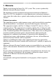
SMART 216 / 232 1. Welcome Thank you for buying the Smart 216 / 232 system. This system is produced by Minicom Advanced Systems Limited. This document provides installation and operation instructions for Minicom’s Smart 216 / 232. It is intended for system administrators and network managers, and assumes that readers have a general understanding of networks, hardware and software.
USER GUIDE 2. Introduction All references throughout this guide to the Smart 216 refer equally to the Smart 232. The two units are functionally the same. The Smart 216 has 16 Server ports and the Smart 232 has 32 Server ports. The Smart 216 extends your KVM (keyboard, video, and mouse) from servers with PS/2 or USB interfaces up to 30m/100ft away. 2 users can control, monitor and manage up to 16 servers simultaneously. You can connect a Power Distribution Unit (PDU) for power management.
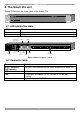
SMART 216 / 232 6. The Smart 216 unit Figure 1 illustrates the front panel of the Smart 216. SMART 216 A MINICOM 1 Power Link 2 Remote Figure 1 Smart 216 ports – side 1 6.
USER GUIDE 7. Pre-installation guidelines • Place cables away from fluorescent lights, air conditioners, and machines that are likely to generate electrical noise • Place the Smart 216 on a flat, clean and dry surface or install in a rack • Ensure that the maximum distance between each computer and the Smart 216, does not exceed 30m/100ft. 7.
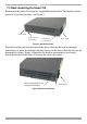
SMART 216 / 232 7.2 Rack mounting the Smart 216 Rack mount the Smart 216 using the supplied Rack-mount kit. The brackets can be placed in 2 possible positions, see Figure 3. Front of unit Position here for front facing Position here for rear facing Rear of unit Figure 3 Bracket positions Place the brackets towards the front of the unit so that the unit can be mounted front facing, or place the brackets towards the rear of the unit so that the unit can be mounted rear facing.
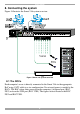
USER GUIDE 8. Connecting the system Figure 5 illustrates the Smart 216 system overview. Figure 5 Smart 216 system overview 8.1 The ROCs Each computer/ server is directly connected to the Smart 216 via the appropriate RoC using CAT5 cable in a star configuration. No external power is needed at the ROCs. The ROCs draw their power from the computer’s keyboard port (ROC PS/2) or from the USB port (ROC USB). The figures below illustrate the ROC PS/2 and ROC USB.
SMART 216 / 232 To computer’s Video card To computer’s keyboard port To computer’s mouse port Figure 6 ROC PS/2 To computer’s Video Card To computer’s USB Port Figure 7 ROC USB 8.1.1 Connecting a ROC PS/2 1. Switch off the server. 2. Connect the ROC PS/2. Figure 8 illustrates the ROC PS/2 connections. 3. Power on the server. You can connect the ROC PS/2 to a powered on computer, but it must be in the following order: 1. Connect the Mouse connector to the computer’s Mouse port. 2.
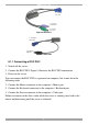
USER GUIDE To Keyboard port Mouse Keybd 100T To Mouse port Parallel Serial A Video ROC PS/2 Serial B CAT5 cable to switch Server port To Video port SCSI PCI 33Mx32b PCI 33Mx32b PCI 33Mx32b PCI 33Mx32b Figure 8 ROC PS/2 connections 8.1.2 Connecting a ROC USB The ROC USB supports Windows 98 SE and later, MAC, SUN and SGI, and all modern Linux distributions. Figure 9 illustrates the ROC USB and its connections. To connect the ROC USB: 1. Connect the Screen connector to the computer’s Video port.
SMART 216 / 232 8.3 Connecting the two KVM consoles Connect a keyboard monitor and mouse to each of the User 1 and User 2 ports as follows: 1. Connect the monitor connectors to the Monitor ports. 2. Connect the keyboard connectors to the Keyboard ports. 3. Connect the mouse connectors to the Mouse ports. 8.4 Connecting to the power supply 1. Using the Power cord provided, connect the Smart 216 to a socket outlet with grounding connection. Only use the power cord supplied with the unit. 2.
USER GUIDE Figure 10 OSD Main window 2. Press F2. The Settings window appears see Figure 11. Figure 11 Settings window In the Settings window you navigate downwards using the Tab key. At the bottom of the window, press tab to go to the top of the window. Change settings by typing in the selected area or by pressing the spacebar – whichever is relevant. 9.2.
SMART 216 / 232 Once the IP address is satisfactory, press ESC twice to save changes and restart the unit. You can now log into the web interface to complete the configuration, as explained below. (Network parameters can also be changed from the web interface as explained on page 14). 10. Logging into the web configuration 1. Open your web browser. 2. Type the Smart 216 system IP address – http or https://IP address/ - and press Enter. The login page appears. 3.
USER GUIDE 10.1 Changing the password To change the password, from the menu click Password, the following appears. Figure 13 Properties Type a new password according to the password policy set - see page 20. Click Apply. 11. Configuring the system From the menu, click Configuration. The Network > Configuration appears, see Figure 14. Figure 14 Network > Configuration page 11.1 Network > Configuration Consult your Network Administrator for the network settings.
SMART 216 / 232 When DHCP is disabled – (Recommended) – You can assign a fixed IP address to the Smart 216. Consult your Network Administrator regarding the use of the DHCP. When DHCP is disabled, enter the IP Address, Subnet Mask, and Default Gateway for LAN, as given by your Network Administrator. These parameters can be configured locally from the OSD as explained on page 11. 11.2 Administration > User Settings From the menu click User Settings, Figure 15 appears.
USER GUIDE User A User can access/control permitted servers. A User has no access to the web configuration interface. View only View only can view the screen of the currently accessed server without keyboard and mouse control. 11.2.1 Adding a user To add a user: and type a name and a password. The password must be at 1. Click least 6 characters – letters or numbers, and must not include the user name, even if other characters are added.
SMART 216 / 232 11.3 Administration > Switch Configuration Assign unique names to the servers connected to the Smart 216, so that users accessing the system can identify the servers easily. To do so: 1. From the menu click Switch Configuration. The Switch Configuration window appears, see Figure 16. Figure 16 Switch Configuration 2. In the Server Name section change the name of the connected servers by selecting the server name and typing a new name. Click changes.
USER GUIDE 11.4 Administration > Power Management Where you have a Minicom Serial Remote Power Switch (SRPS), connect it to the RPS port of the Smart 216. Configure the Power Management switch as follows: 1. From the menu, click Power Management. The Power Management window appears, see Figure 16. Figure 17 Power Management 2. Select the number of sockets on the power management switch in the Number of Sockets drop-down menu (SRPS has 8) 3. Click .
SMART 216 / 232 12. Administration > User Targets Define the access rights of each user separately. To do so: 1. From the menu click User Targets. The User Targets Configuration window appears, see Figure 18. Figure 18 User Targets Configuration 2. Select a user from the User drop-down menu. 3. Check the servers the user can access (according to his access permissions). To select all servers, press . 4. Click Apply, the selection is saved. 5. Repeat the above steps for other users.
USER GUIDE 13. Security > Settings Configure the security features, such as Account Blocking, Password Policy and Idle Timeout, as explained below. From the Security section click Settings, the Security Settings appear, see Figure 19. Figure 19 Security Settings The Security Settings fields: Account Blocking – decide on the number of attempts to login with a wrong username or password after which there is a time lock or a total block.
SMART 216 / 232 14. Security > SSL Certificate You can install an SSL certificate. To do so: From the menu, select SSL Certificate, the install SSL Certificate page appears, see Figure 20. Figure 20 Install SSL Certificate page Certificate File - Browse to locate the cer file (.ssl format). Private Key File - Browse to locate the private key file (.pem format). Key Password – Type the Key password. Click . The certificate installs. The device restarts automatically. 15.
USER GUIDE 16. Maintenance > RICCs/RoCs Upgrade Upgrade the ROC firmware to take advantage of new features. Download the firmware from the Support section of Minicom’s website –www.minicom.com. Save the firmware file on the Client computer. 1. From the menu select RICCs/RoCs Upgrade. The RICCs/RoCs Upgrade window appears showing the current firmware version see Figure 22. 2. Select the servers connected to the ROCs you wish to upgrade. Click to select all. 3.
SMART 216 / 232 To restore factory settings: 1. From the menu select Restore Factory Settings. Restore Factory Settings appears see Figure 23. Figure 23 Restore factory settings 2. Check the box if you want to preserve Network settings. 3. Click . The unit restarts. 18. Set Time & Date The time and date set is used when recording log events (see page 25). To set the time and date: From the menu, select Time & Date, Figure 24 appears.
USER GUIDE 19. Backup & Restore You can backup all configuration data and restore it at a later date. To do so: From the menu select Backup & Restore, Figure 25 appears. Figure 25 Backup & Restore . And save the file. To backup the configuration data, click To restore the configuration data, browse to locate the file and click device restarts. , the 20. Saving changes and logging out To save any configuration changes click the relevant button on the current page.
SMART 216 / 232 21. Event log To see a log of all system events: From the Targets page menu – see Figure 12 on page 13 – select Event Log, the following appears.
USER GUIDE 22. Operating the system via the OSD To display the OSD: 1. From the local keyboard, press the left Shift key twice. The OSD Main window appears. See Figure 27. Server status: Off Port number appears here Server status: On Instruction keys Figure 27 OSD Main window 22.1 Navigating the OSD Main window To navigate up and down use the Up and Down arrow keys. To exit the OSD press Esc. 22.2 Selecting a computer To select a computer: 1. Navigate to the desired computer line.
SMART 216 / 232 22.3 Power management hotkey – left Shift, F12 To power manage a server connected to a power management switch: 1. Navigate to the computer line you desire to power manage. 2. Press left Shift, F12. The Power Control dialog box appears, see Figure 28. Note! If you change the OSD hotkey from Shift, Shift to Ctrl, Ctrl, then the power management hotkey becomes left Ctrl, F12. Figure 28 Power Control dialog box 3.
USER GUIDE 22.5 Tuning – F5 You can tune the image of any computer screen from the Main window. To adjust the screen image: 1. Navigate to the computer line you wish to adjust. 2. Press F5. The screen image of the selected computer appears, together with the Image Tuning label, see Figure 30. Figure 30 Image Tuning label 3. Adjust the image by using the Right and Left Arrow keys. 4. When the image is satisfactory, press Esc. Note! Picture quality is relative to distance.
SMART 216 / 232 From In the Settings window you can do the following: HOT KEY – By pressing Shift, Shift the OSD appears. You can replace Shift, Shift with any of the following: • Ctrl, Ctrl • Ctrl, F11 • Print Screen Press the Spacebar to toggle between options. To display the OSD press the new hotkey. KEYBOARD LANGUAGE - Press the Spacebar to toggle between the language options. It can be changed to French or German. 22.
USER GUIDE 23. Technical specifications Server operating systems Windows, Novell, Linux, SUN Solaris Resolution Up to 1600 x 1200 @ 85Hz Distance from Switch to ROCs Up to 30m/100ft. System cable CAT5 UTP/FTP Solid Wire 2x4x24 AWG Ethernet – RJ45 – 10/100 Mbit/sec autosensing RPS – RJ45 Connections 2 x KVM connection – Screen HDD15, Keyboard./Mouse – 2 x USB Servers – RJ45 x 16 for the Smart 216 and RJ45 x 32 for the Smart 232 Weight 2.343Kg / 5.
SMART 216 / 232 24. Safety This device contains no serviceable parts. Any servicing of the device must be performed by an authorized Minicom Technician in a Minicom authorized Service Center. 25. User guide feedback Your feedback is very important to help us improve our documentation. Please email any comments to: ug.comments@minicom.com Please include the following information: Guide name, part number and version number (as appears on the front cover). 26.
USER GUIDE Regional Offices Germany France Italy Kiel Vincennes Rome Tel: + 49 431 668 7933 info.minicom-germany@minicom.com Tel: + 33 1 49 57 00 00 Tel: + 39 06 8209 7902 England China info.france@minicom.com info.italy@minicom.com Asia Pacific / S. Korea Beijing Tel: + 44 121 288 0608 Tel: +86 21 6445 3181 Tel: +972 2 535 9618 info.uk@minicom.com Info.china@minicom.com info.ap@minicom.com www.minicom.
SMART 216 / 232 33