
User guide


SMART CAT5 SWITCH
5
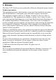
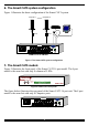
6. The Smart CAT5 system configuration
Figure 1 illustrates the basic configuration of the Smart CAT5 system.
Computer 1
Smart CAT5 Switch
Computer 16
RICC
RICC
POWER
100-250 VAC 50/60 Hz
12345678
101112131415169
COMPUTER
www.minicom.com
Figure 1 The Smart CAT5 system configuration
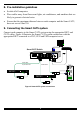
7. The Smart CAT5 models
Figure 2 illustrates the front panel of the Smart CAT5 16 port model. The 8 port
model is the same but with only 8 columns of LEDs.
SMART
SELECT
CAT5
SWITCH
MINICOM
10111213141516123456789
Selected
CPU on
Figure 2 Smart CAT5 front panel
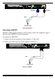
The figure below illustrates the rear panel of the Smart CAT5 16 port unit. The 8 port
model is the same but with only 8 Computer ports.
POWER
100-250 VAC 50/60 Hz
12345678
101112131415169
COMPUTER
www.minicom.com
Figure 3 Smart CAT5 16 port rear panel