Smart CAT5 Switch 8 and 16 Port User Guide w w w . m i n i c o m . c o m International HQ North America Europe Jerusalem, Israel Linden, NJ, USA Dübendorf, Switzerland Tel: + 972 2 535 9666 minicom@minicom.com Tel: + 1 908 4862100 info.usa@minicom.com Tel: + 41 1 823 8000 info.europe@minicom.com Customer support - support@minicom.com 5UM20110 V1.
SMART CAT5 SWITCH Table of Contents 1. Welcome ......................................................................................................... 3 2. Introduction..................................................................................................... 4 3. Features .......................................................................................................... 4 4. System components ....................................................................................... 4 5.
USER GUIDE 42. Read Configuration....................................................................................... 27 43. Write Configuration....................................................................................... 27 44. Renaming a computer................................................................................... 28 45. The Edit menu............................................................................................... 28 46. Logo and Passwords ........................
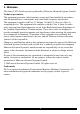
SMART CAT5 SWITCH 1. Welcome The Smart CAT5 Switch system is produced by Minicom Advanced Systems Limited. Technical precautions This equipment generates radio frequency energy and if not installed in accordance with the manufacturer’s instructions, may cause radio frequency interference. This equipment complies with Part 15, Subpart J of the FCC rules for a Class A computing device.
USER GUIDE 2. Introduction Access and control multiple multi-platform computers from one Keyboard Video Mouse (KVM) console with the Smart CAT5 Switch (Smart CAT5) system. The Smart CAT5 comes in 8 and 16 port models. Connect up to 8 computers to the 8 port model, and up to 16 to the 16 port model. 3.
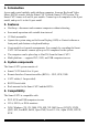
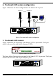
SMART CAT5 SWITCH 6. The Smart CAT5 system configuration Figure 1 illustrates the basic configuration of the Smart CAT5 system. Computer 16 Computer 1 RICC RICC www.minicom.com COMPUTER 9 10 11 12 13 14 15 16 1 2 3 4 5 6 7 8 POWER 100-250 VAC 50/60 Hz Smart CAT5 Switch Figure 1 The Smart CAT5 system configuration 7. The Smart CAT5 models Figure 2 illustrates the front panel of the Smart CAT5 16 port model. The 8 port model is the same but with only 8 columns of LEDs.
USER GUIDE 8. Pre-installation guidelines · Switch off all computers · Place cables away from fluorescent lights, air conditioners, and machines that are likely to generate electrical noise · Ensure that the maximum distance between each computer and the Smart CAT5, does not exceed 10m/33ft 9. Connecting the Smart CAT5 system Connect each computer to the Smart CAT5 system using the appropriate RICC and CAT5 cables.
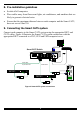
SMART CAT5 SWITCH The RICCs The RICCs draw their power from the computer’s keyboard port (RICC PS/2, SUN) or from the USB port (RICC USB). Connecting a PS/2 RICC Figure 5 illustrates the RICC. To connect the PS/2 RICC: 1. Connect the Screen connector to the computer’s Video card. 2. Connect the Keyboard connector to the computer’s Keyboard port. 3. Connect the Mouse connector to the computer’s Mouse port.
USER GUIDE To Computer’s Video Card To Computer’s Keyboard Port RICC CAT5 cable to Smart CAT5 Computer port Figure 6 SUN RICC Connecting a USB RICC The RICC USB supports Windows 98 SE and later, MAC, SUN and SGI. Figure 7 illustrates the USB RICC and its connections. To connect the USB RICC: 1. Connect the Screen connector to the computer’s Video card. 2. Connect the USB connector to the computer’s USB port.
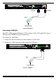
SMART CAT5 SWITCH Connecting the CAT5 cables 1. Connect one connector to the RICCs RJ45 port. 2. Connect the other connector to one of the Smart CAT5’s Computer ports. 3. Follow the above 2 steps for each computer. Connecting the KVM console To connect a KVM console to the Smart CAT5: 1. Connect the monitor’s connector to the Smart CAT5’s Monitor port. 2. Connect the keyboard’s connector to the Smart CAT5’s Keyboard port. 3. Connect the mouse’s connector to the Smart CAT5’s Mouse port. 10.
USER GUIDE Circuit overloading When connecting the equipment to the supply circuit, consider the effect that overloading of circuits might have on over-current protection and supply wiring. Reliable earthing of rack-mounted equipment should be maintained. Give attention to supply connections other than direct connections to the branch circuit (e.g. use of power strips). 13. Rack mounting the Smart CAT5 Length of the screws used for connection of the bracket to the Smart CAT5 unit shall not exceed 5 mm.
SMART CAT5 SWITCH 14. Rack mounting the RICCs You can attach the RICCs to a server rack or computer using the Velcro strips provided. Or connect it using the bracket provided. The figure below illustrates the bracket.
USER GUIDE 15. Cascading Smart CAT5 switches You can cascade the Smart CAT5 system. You do so by connecting the lower level Smart CAT5 Switches to RICCs. Follow the connections as illustrated in the figure below. With the Smart CAT5 16 Port model, connect up to up to 256 computers through cascading. A lower level Switch must have a different hotkey to display its OSD than a higher level switch. Changing the OSD display hotkey is explained on page 16 below.
SMART CAT5 SWITCH 16. Operating the Smart CAT5 system Switch between the connected computers by either · The front panel Select buttons · Keyboard hotkeys · The OSD (On Screen Display) or Control software The OSD is also the place to adjust various settings as explained below. When switching computers the illuminated LED of the top bank indicates which computer is currently selected. 17. The keyboard hotkeys To switch to the next computer forwards press Shift then, +.
USER GUIDE 19. Navigating the OSD To navigate up and down use the Up and Down arrow keys. To jump from one column to the next (when relevant) use the Tab key. To exit the OSD or return to a previous window within the OSD press Esc. 20. Selecting a computer To select a computer: 1. Navigate to the desired computer line. 2. Press Enter. The selected computer is accessed. An confirmation label appears showing which computer is accessed.
SMART CAT5 SWITCH 22. The General settings With the GENERAL line highlighted, press Enter. The General settings window appears see Figure 13. Figure 13 The General Settings window From this window you can do the following: Security The OSD comes with an advanced password security system that contains 3 different security levels. Each security level has different access rights to the system.
USER GUIDE Activating password protection By default OSD access is not password protected. Only the Administrator can password-protect the OSD or disable password protection. To do so: 1. In the General settings window navigate to the Security line. 2. Press the Spacebar to toggle between Security On and Off. The password box appears. 3. Type the Administrator’s password (default is “admin”). 4. Press Enter. The new security status is set. If you forget the Administrator's password, go to www.minicom.com.
SMART CAT5 SWITCH To change a lower level hotkey: 1. Connect a keyboard and monitor to the lower level Switch and press Shift, Shift. Its OSD appears. 2. Press F2 and select GENERAL. The General settings window appears. 3. Navigate to the HOTKEY line. 4. Choose a different hotkey than the hotkey of the of the top layer switch. Toggle between the options using the Spacebar.
USER GUIDE 23. F7 Defaults Press F7 to return the OSD to the factory default settings. Note! All changes made will be removed. 24. The Ports settings From the General Settings, return to the Settings window by pressing Esc. Navigate to the Ports line and press Enter. The Ports settings window appears see Figure 14. Figure 14 Ports Settings window Editing the computer name In this window you can edit the computer names with up to 15 characters.
SMART CAT5 SWITCH (HKEY) hotkey - Cascading When there are cascaded switches, and the lower level Switch has had its OSD display hotkey changed, you must do the following: Adjust the HKEY setting in the Ports Settings window of the higher level switch to reflect the lower level switch’s new hotkey: E.g. in Figure 14 above a Smart CAT5 switch is connected to port #3 and its display hotkey is Ctrl, F11. To reflect the new hotkey: 1.
USER GUIDE 2. Place the cursor over one of the 3 digits and type a new number. Enter a leading zero where necessary. For example, type 040 for 40 seconds. Typing 999 in the LBL column displays the label continuously. Typing 000 – the label will not appear. Typing 999 in the T/O column disables the Timeout function. Typing 000 – the Timeout function works immediately. Typing 999 in the SCN column displays the screen for 999 seconds. Typing 000 – the computer screen is skipped. 26.
SMART CAT5 SWITCH 27. Security In the Settings window navigate to the Security line and press Enter. The Security settings window appears see Figure 17. Figure 17 The Security settings window The ‘T’ column on the right hand side stands for Type of password. There can only be 1 Administrator password, 1 Supervisor password, and 6 User passwords. To change a user name or password: 1. Navigate to the desired line and column. 2. Type a new user name / password.
USER GUIDE Please note! All the functions set out in the Help window are performed from the Main window. The Help window is merely a reminder of the hotkeys and their functions. 29. Scanning computers– F4 Where necessary adjust the scan time in the Time Settings window, see above. To activate scanning: 1. Press Shift twice to open the OSD. 2. Press F4. Your screen displays each active computer sequentially, with the Scan label appearing in the top left corner. To deactivate scanning: Press F4. 30.
SMART CAT5 SWITCH 4. Press Esc to save and exit. 32. Using the Control software As an alternative to the OSD you can operate the Smart CAT5 system with the Control software located on the Marketing & Documentation CD. With the OSD you operate the system and view the computer screens on the same monitor. The Control software requires 2 monitors 1 for the software and 1 to view the computer screens.
USER GUIDE 34. Connecting the RS232 Serial cable To run the software, connect the RS232 Serial cable to the computer containing the software, and to the Smart CAT5. See the figure below. P110 SD Computer screens appear here Smart CAT5 Switch 10 11 12 13 14 15 16 1 2 3 4 5 6 7 8 POWER 100-250 VAC 50/60 Hz www.minicom.
SMART CAT5 SWITCH 35. Installing and running the Control software Note! The system must be fully connected BEFORE running the Control software. Failure to first connect the system will lead to the software working in demo mode. To install the software: 1. Insert and start the Marketing & Documentation CD. 2. Choose Smart CAT5 Switch Softpack. The Smart CAT5 Switch Softpack window appears. 3. Choose Install Smart CAT5 RS232 Control Software. Once installed, a shortcut icon appears on the Desktop . 4.
USER GUIDE 36. Computer icons Icon Meaning Computer is connected and switched on Computer is switched off or unconnected Computer that you are presently connected to Connected and switched on computer with a Local Workstation attached and presently being used locally. After remaining idle for the Timeout period, it changes to yellow. When you first open the Control window the software automatically gets the status of the system, including the security access settings. 37.
SMART CAT5 SWITCH 39. Selecting a computer To select a computer: Click on the computers icon. The system switches to that computer. The connected . Control and monitor the selected computer icon appears with a red background from the keyboard and mouse connected to the Smart Switch. 40. The toolbar buttons The toolbar buttons are explained below. 41.
USER GUIDE 44. Renaming a computer To rename a computer: 1. Type the new name in the box below the computer icon. to send the new name to the system. 2. Click Or click Save or Save As from the File menu to save the change in a file and not alter the OSD names. 45. The Edit menu You can edit all OSD fields. Edit the following from the Edit menu. · Logo · Passwords · Settings 46. Logo and Passwords You can edit the logo that appears at the top of the OSD window.
SMART CAT5 SWITCH 47. Settings Choose Settings from the Edit menu. The Computers’ Properties box appears. See Figure 24. Figure 24 The Computers’ Properties box Here you can edit all the data that can be edited in the OSD. This includes: Scan times, Timeout, Confirmation label display time, Keyboard type/mode, User access, Password mode, Autoskip mode, and Switch/System hotkey. These features are explained in the OSD section of this Appendix. To edit a setting: 1.
USER GUIDE 48. Loading a saved configuration To load a saved configuration: From the File menu choose Open. 49. Reminder! All changes done with the Control software are only reflected in the OSD AFTER pressing . 50. The factory default settings To revert to the factory default settings: On the toolbar press . There is no need to press . 51. Password protection When the Smart CAT5 system is password protected, the Control software behaves in exactly the same way as the OSD.
SMART CAT5 SWITCH User (Status U) There are 6 different Users in the Smart CAT5 system. Each User has a Profile that defines the access level to different computers. There are 3 different access levels. These are: · Y – Full access to a particular computer · V –Viewing access only, to a particular computer (No keyboard/mouse functionality) · N – No access to a particular computer The Administrator defines the desired access levels of each User Profile. This is done in the Setting box.
USER GUIDE 55. Connecting the RS232 Serial cable To run the software, connect the RS232 Serial cable to the computer containing the software, and to the Smart CAT5 Switch. See page 24. 56. Installing the software To install the Smart CAT5 Switch Update software: 1. Insert the Marketing & Documentation CD. The CD menu runs automatically. 2. Choose Smart CAT5 Switch Softpack. 3.
SMART CAT5 SWITCH The table below explains the functions of the buttons and boxes in the Smart CAT5 Switch Update window. Button or Box Function Selects all RICCs Unselects selected RICCs Starts firmware download Displays the firmware version number Displays the hardware version number Cancels selected function System time Displays download status Name of Update file 2. From the Options menu choose Com Port. The Com Port box appears. See Figure 27. Figure 27 The Com Option box 3.
USER GUIDE The OSD version number To verify the OSD version number: 1. Open the Smart CAT5 Switch Update program. 2. In the Switch Unit box, check the OSD option. See Figure 26. 3. Click . The version number appears in the Switch box. The H/W Version button is grayed out, as there is no hardware relevant to the OSD. The Smart CAT5 Manager version number To verify the Smart CAT5 version number: 1. Open the Smart CAT5 Switch Update program. 2.
SMART CAT5 SWITCH 60. Updating the firmware Warning! Never switch off any computer connected to the Smart CAT5 system during the updating process. To update the firmware: 1. Open the Smart CAT5 Switch Update program. 2. In the Smart CAT5 Switch Update window, check the appropriate option in the Switch Unit box or the desired RICC. 3. From the File menu, choose Open. The Open box appears. See Figure 28. 4. Navigate to the folder that contains the firmware update file.
USER GUIDE NOTE! The Reset function does not affect the parameters of the unit settings. Resetting the Switch or RICC units To reset the Switch or RICC units: 1. For the Switch, check the Smart CAT5 Switch option in the Switch Unit box. For the RICCs, check one or more RICCs in the RICC Units box. 2. From the Options menu choose Advanced / Reset. The units reset. The system should now be operational. 62. RICC SUN keyboard emulation By default the RICC SUN supports US English keyboard emulation.
SMART CAT5 SWITCH 64. USB / SUN Combo keys The connected PS/2 keyboard does not have a special SUN keypad to perform special functions in the SUN Operating System environment. So when a RICC USB or SUN is connected to a SUN computer, the RICC emulates these SUN keys using a set of key combinations called Combo keys. See the table below.
USER GUIDE 65. Technical specifications Operating systems and Platforms DOS, Windows LINUX, UNIX, QNX, SGI, FreeBSD, BeOS, Novell 3.12-6, SUN Mouse PS/2, Wheel mouse, Intellimouse, 5-button mouse Resolution 1600x1200@75Hz System cable CAT5/ 5E/ 5+/ 6/ or 7 cables. FTP or UTP 2x4x24 AWG solid wire Transmission distance Up to 10m/33ft Smart CAT5 Switch Dimensions – 8/16 port 215.0 x 122.0 x 41.5mm / 8.46 x 4.80 x 1.63in Weight – 8/16 port Product – 920g / 2lbs Shipping – 1.87Kg / 4.
SMART CAT5 SWITCH Regional Offices Germany France Italy Kiel Vincennes Rome Tel: + 49 431 668 7933 info.germany@minicom.com Tel: + 33 1 49 57 00 00 info.france@minicom.com Tel: + 39 06 8209 7902 info.italy@minicom.com www.minicom.