
User guide
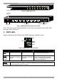


SERIAL REMOTE POWER SWITCH
6
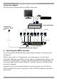
Connection diagram
The figure below illustrates the basic SRPS connections.
Legacy KVM switch
Serial
Serial RPS Manager
- Power ports
- KVM ports
RING ON
& RESET
iLINK
i i i
i
i i
L
N
K
P
W
R
RS232
I
0
A B C
D E F
H
9
1
10
99
1112
95
1314
67
1516
8
G
ii
RS232 Console Command
12
CDEFGH
Serial cable
To terminal or
computer’s Serial
port
345678
BA
hp1925
Auto12
Figure 6 SRPS connection diagram
8. Operating the SRPS manually
You can operate the SRPS manually using the manual buttons on the front panel.
See Figure 4.
When a power outlet is in manual mode, you cannot operate it via the Serial
connection. When the green LED is off, the outlet is in manual mode. When it is on
the outlet is in Serial mode. To change from manual mode to Serial mode and vice
versa, press and hold the manual button for 3 seconds. The green Led flashes and
the mode is changed.
In manual mode, press the manual button to switch the outlet on or off. The red
LED on indicates the socket is powered on. The red LED off indicates the socket is
powered off.