
User guide


SERIAL REMOTE POWER SWITCH
4
RING ON
& RESET
iLINK
i i i i i i
I
0
A B
C D E F
H
9
1
10
99
1112
95
1314
67
1516
8
G
ii
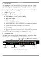
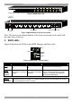
Figure 2 SRPS Slave front
INPUT
D
C
B
G
F
H
/
/
/
E
A/
INPUTHGFEDCBA
AC input
Circuit
breaker B
Power output
RS232 communication
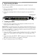
Figure 3 SRPS Manager and Slave rear panel
Note: The letter on the manual buttons at the front corresponds to the outlet with
the same letter at the rear.
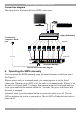
5. SRPS LEDs
Figure 4 illustrates the LEDs on the SRPS Manager and Slave units.
i
A
9
1
Red
Green
Yellow
Manual
button
Figure 4 SRPS LEDs + manual button
LED On Off Flashing
Red
Power
The outlet is powered
on
The outlet is powered
off
The outlet has an internal fault.
Green
Remote
control
The outlet is controlled
Serially
The outlet is controlled
manually
To change from Serial to manual
control. Press and hold the manual
button for 3 seconds. During these 3
seconds the LED flashes
Yellow
ID number
Indicates the SRPS ID number. The master displays all the connected SRPS ID numbers.
The slave displays its own ID number