
User guide


USER GUIDE
13
3. Connect further iLink cables to the iLINK ports of the rest of the Slaves.
4. Connect the Power cord of each server to the Output ports of SRPS units.
5. Operate the system as set out on page 7.
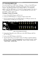
12. Connecting the SRPS to the IP Control
You can connect the SRPS to the IP Control and then manage the power of the
servers seamlessly via they IP Control remote GUI.
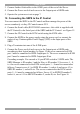
6. Connect the Serial cable (RS232-RJ45 connectors - this cable is supplied with
the IP Control) to the Serial port of the SRPS and the IP Control– see Figure 15.
7. Connect the IP Control to the KVM switch using the KVM cable.
8. Connect the SRPS to the power supply using the power cord, or connect the
socket of any Uninterruptible Power Supply (UPS) to the Input ports of the
SRPS.
9. Plug a Terminator into one of the iLINK ports.
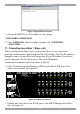
1. Connect the Power cord of each server to the Output ports of SRPS units
according to their logical number. In Figure 15 the server connected to KVM
port 1 must be connected to SRPS Output port A. The server connected to KVM
port 2 must be connected to SRPS Output port B etc
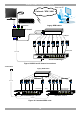
Cascading example. You cascade a 16 port KVM switch to 2 SRPS units. The
SRPS Manager is ID number 1 and the Slave is ID number 2. So servers 1 – 8,
i.e. the servers connected to the KVM switch ports 1 – 8 must be connected as
follows: Connect server # 1 to SRPS ID number 1, socket A and server # 2 to
SRPS ID number 1, socket B etc. The servers connected to the KVM switch
ports 9 – 16 must be connected as follows: Server # 9 to SRPS ID number 2,
socket A, server # 10 to SRPS ID number 2, socket B, etc. See Figure 16.