Serial Remote Power Switch User Guide w w w . m i n i c o m . c o m International HQ North American HQ European HQ Jerusalem, Israel Linden, NJ, USA Dübendorf, Switzerland Tel: + 972 2 535 9666 minicom@minicom.com Tel: + 1 908 486 2100 info.usa@minicom.com Tel: + 41 44 823 8000 info.europe@minicom.com Technical support - support@minicom.
USER GUIDE Table of Contents 1. 2. 3. 4. 5. 6. 7. 8. 9. 10. 11. 12. 13. 14. Welcome .................................................................................................. 2 Introduction............................................................................................. 3 SRPS components .................................................................................... 3 The SRPS units.........................................................................................
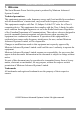
SERIAL REMOTE POWER SWITCH 1. Welcome The Serial Remote Power Switch system is produced by Minicom Advanced Systems Limited. Technical precautions This equipment generates radio frequency energy and if not installed in accordance with the manufacturer’s instructions, may cause radio frequency interference. This equipment complies with Part 15, Subpart J of the FCC rules for a Class A computing device.
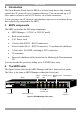
USER GUIDE 2. Introduction The Serial Remote Power Switch (SRPS) is a Serial ready device that remotely controls the AC power of up to 8 connected devices. You can cascade up to 15 Slave units to control a total of 128 devices via a Serial connection. A user can power on/off, reboot or safe shutdown any server or hardware device that is physically connected to the SRPS. 3.
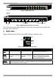
SERIAL REMOTE POWER SWITCH RING ON & RESET i iLINK i A i 1 9 i C B 9 10 i D 9 11 9 12 i E i F 5 13 i G 6 14 I 0 H 7 15 8 16 Figure 2 SRPS Slave front Circuit breaker B INPUT INPUT H G F E D C B A Power output AC input D/ H C/ G B/ F A/ E RS232 communication Figure 3 SRPS Manager and Slave rear panel Note: The letter on the manual buttons at the front corresponds to the outlet with the same letter at the rear. 5.
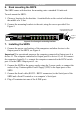
USER GUIDE 6. Rack mounting the SRPS The SRPS comes with brackets for mounting onto a standard 19-inch rack. To rack mount the SRPS: 1. Choose a location for the brackets. A notched hole on the vertical rail denotes the middle of a U slot. 2. Connect the mounting brackets to the unit, using the screws provided. See Figure 5.
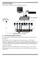
SERIAL REMOTE POWER SWITCH Connection diagram The figure below illustrates the basic SRPS connections. ut o A hp 19 25 1 2 Legacy KVM switch To terminal or computer’s Serial port Serial cable 1 A RING Serial ON & RESET B iLINK 2 3 4 C D 5 6 E F i RS232 PW R LN i 7 G i i 8 i i H i i K RS232 C onsole Command A 1 9 B 9 10 D C 9 11 9 12 E 5 13 F 6 14 G 7 15 - KVM ports H - Power ports I 0 8 16 Serial RPS Manager Figure 6 SRPS connection diagram 8.
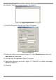
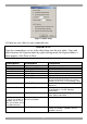
USER GUIDE 9. Operating the system via Serial connection 5. Use a Serial terminal or a Serial emulation program via a computer to connect to the SRPS Manager. The screen shots below use Windows Hyperterminal. 6. Choose Start/Programs/Accessories/Communications/Hyperterminal. 7. When prompted enter a name and click OK. The Connect To box appears. See Figure 7. Figure 7 Connect To box 8. Fill in the connection details.
SERIAL REMOTE POWER SWITCH 10. Click OK. The Hyperterminal appears. See Figure 9. Figure 9 Hyperterminal 11. Click File/Properties, Settings tab. Figure 10 appears. Figure 10 Settings tab 12. Ensure the values are as set out in Figure 10. Check Windows keys and select Auto detect for Emulation. 13. Click the ASCII setup button. Figure 11 appears. 14. Ensure the values are as set out in Figure 11. Check the 2 top fields, and change Character delay to 1. 15. Click OK.
USER GUIDE Figure 11 ASCII setup 16. Open any text editor to type commands into. IMPORTANT! Type the commands as set out in the table below into the text editor. Copy and paste them into the Hyperterminal by right-clicking inside the Hyperterminal, a menu appears, click Paste to Host.
SERIAL REMOTE POWER SWITCH Description Command Set real time ^isS020TMEyyyy,mm,dd,n,HH yyyy is year MM mm is month dd is date n is Monday to Sunday (1-7) HH is hours MM is minutes ^isS018SUDX,X,X,X,X,X,X,X Outlet (1-8) Set Safe shutdown enable/disable, X 1 is enable, o is disable Get safe shutdown setting status Set Power Return SW on delay time, n is 1-8, SSSSS is seconds. Max 65535 sec.
USER GUIDE 10. Cascading SRPS units You can cascade up to 16 SRPS units (1 Manager + 15 Slaves). Each SRPS must have its own unique ID number and the ID numbers must also be in a logical sequence. The default ID number of the Manager SRPS is 1. The default ID number of all Slave SRPS units is 16. So to be in a logical sequence where there is 1 Slave, change the Slave ID number to 2. For each additional Slave give it the next number - ID no 3, then 4 etc. Changing 1 Slave’s ID number 1.
SERIAL REMOTE POWER SWITCH Figure 13 Hyperterminal response 7. Change the SRPS Slave’s ID number to 2 by pasting: ^isS005ADR16^isS005CFG02 . 8. Paste ^isP003EAD. HyperTerminal responds with ^iSWITCH01, ^iSWITCH02. 11. Cascading more than 1 Slave unit When cascading more than 1 Slave, connect the Slaves one at a time in the procedure outlined above, and change the Slave ID number.
USER GUIDE 3. Connect further iLink cables to the iLINK ports of the rest of the Slaves. 4. Connect the Power cord of each server to the Output ports of SRPS units. 5. Operate the system as set out on page 7. 12. Connecting the SRPS to the IP Control You can connect the SRPS to the IP Control and then manage the power of the servers seamlessly via they IP Control remote GUI. 6.
SERIAL REMOTE POWER SWITCH User over IP Internet / VPN / LAN ut o A 1 2 hp 1 92 5 Legacy KVM switch LAN MINICOM IP Control KVM cable IP CONTROL KVM In Ser ial KVM ports 3.
USER GUIDE 13. Operating the SRPS via IP Control 1. Configure the IP Control to work with the SRPS. From the IP Control Administration menu click Serial Settings the Serial Settings appear, see Figure 17. See the IP Control User Guide for more details. Figure 17 Serial Settings 2. Check the Assign to SRPS box and save. The system is ready to work. 3. From the Toolbar, click servers/devices appears. , or right-click . A list of connected 4. Click the desired server or Serial device.
SERIAL REMOTE POWER SWITCH 14.
USER GUIDE User Guide Feedback Your feedback is very important to help us improve our documentation. Please email any comments to: ug.comments@minicom.com Please include the following information: Guide name, part number and version number (as appears on the front cover).
SERIAL REMOTE POWER SWITCH Regional Offices Germany France Italy Kiel Vincennes Rome Tel: + 49 431 668 7933 info.germany@minicom.com Tel: + 33 1 49 57 00 00 info.france@minicom.com Tel: + 39 06 8209 7902 info.italy@minicom.com England Camberley Tel: + 44 (0) 1276 25053 info.uk@minicom.com www.minicom.