
Installation guide


INSTALLATION GUIDE
Note! IPMI V1.5 is only supported by server systems manufactured in 2002
onwards.
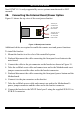
28. Connecting the Internal Reset/Power Option
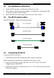
Figure 19 shows the top view of the reset/power bracket.
To Reset pin
on Mainboard
To front panel
Reset switch
To Power On pin
on Mainboard
To front panel
Power switch
Figure 19 Reset/power bracket
Additional cables are required to enable the remote reset and power functions.
To install the bracket:
1. Mount the bracket in a free slot of the controlled system.
2. Find and disconnect the cable connecting the front panel reset button to the
main board.
3. Connect the cable to the pin connector on the bracket as shown in Figure 19.
4. Take the red/black reset cable and connect one end to the Motherboards reset
jumper connector and the other end to the bracket connector.
5. Find and disconnect the cable connecting the front panel power button and the
Motherboard.
6. Connect it to the pin connector on the bracket.
7. Take the red/black power cable and connect one end to the Motherboard 's
power jumper connector and the other end to the bracket connector.
8. Connect the bracket to the MX IP Serial port 2 using the supplied SUB-D 9 to
SUB-D 9 connector.
18