Phantom Operating Guide International HQ North American HQ German Europe Italy Jerusalem, Israel Tel: + 972 2 535 9666 minicom@minicom.com Linden, New Jersey Tel: + 1 908 4862100 info.usa@minicom.com Zurich, Switzerland Tel: + 41 1 455 6220 info.german@minicom.com Rome Tel: + 39 06 8209 7902 info.italy@minicom.com www.minicom.com Customer support - support@minicom.com V1.
Introduction Chapter 1: Introduction The Phantom system from Minicom is a CAT5 based Distributed KVM Switching system for server management. Connect up to 64 computers in the Phantom system. The system can be managed and controlled by 1 or 2 users. For 2-user control see the MX II Guide.
The Phantom configuration Features The Phantom system gives you: • Control and monitor mixed, multi-platform server environments of up to 63 remote computers from 1 or 2 Manager position • Advanced On Screen Display management (including multi-layer security), and BIOS level access • The option to connect a keyboard, video and mouse to any Remote PCI card computer – referred to as a Local Workstation • A total distance of up to 110m/360ft between the Manager computer and the last connected Remote co
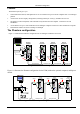
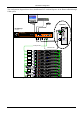
Introduction The configuration diagram below shows both Remote PCI cards and Specters in the Phantom UPM system. P 1 10 SD UPM USER POWER COMPUTER SYSTEM SERVICE w w w.min ico m.com 85-265VAC 50/60 Hz Optional 3 in 1 Cable CAT5 System Cable RS232 Serial Cable ProLiant DL360 OUT PHANTOM Specter Link Active IN 9.1 - GB 10k ULTRA2 SCSI 9.1 - GB 10k ULTRA2 SCSI MINICOM www.minicom.com ProLiant DL360 OUT PHANTOM Specter Link Active IN 9.1 - GB 10k ULTRA2 SCSI 9.
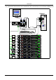
The Phantom configuration The configuration diagram below shows both Remote PCI cards and Specters in the Phantom RackManager UPM system. P110 SD Optional RackManager Phantom Universal Manager COMPUTER MINICOM SERVICE w ww . m in ic o m.c o m SYSTEM 3 in 1 CPU cable CAT5 System cable RS232 Serial cable ProLiant DL360 PHANTOM Spe c te r Link Active 9.1 - GB 10k ULTRA2 SCSI 9.1 - GB 10k ULTRA2 SCSI MINICOM w ww. minicom .com ProLiant DL360 PHANTOM Spe c te r Link Active 9.
OSD Technology OSD Technology The Phantom system superimposes a menu on the Manager position computer screen. This On-Screen-Display (OSD) consists of three sections. From the OSD, you activate various functions discussed in the Operating guide. The Local Workstation Option When using the Phantom Remote PCI cards, you have the option of working at the remote computer by connecting a keyboard, video, and mouse to it. This is called the Local Workstation option.
The OSD functions Chapter 2: The OSD functions The Phantom system is controlled and monitored through an On-Screen-Display (OSD) on the Manager screen. When the Phantom Manager is the UPM you can also use Minicom’s Control software or equivalent software. The Control software is discussed in chapter 4. The OSD contains a number of different windows that are accessed using Hot-keys. Each window has its own special function. Displaying the OSD To display the OSD: Press Shift, Shift.
The hotkey functions Selecting a Computer To select a computer: 1. Navigate to the desired computer with the Up and Down Arrow keys. Or Type the computer number. It will appear in the “SELECT COMPUTER” line. See Figure 2-1. 2. Press Enter. The selected computer’s screen replaces the Manager’s screen. A Confirmation label appears showing which computer is accessed. See Figure 2-2. Control and monitor the computer from the Manager KVM position.
The OSD functions Move Label - F1 Position the Confirmation label – Figure 2-2 above – anywhere on the screen. To position the label: 1. Navigate to the desired computer using the Up and Down arrow keys. 2. Press F1. The selected screen image and Identification label will appear. 3. Use the arrow keys to move the label to the desired position. 4. Press Esc to save and exit. Edit Mode window - F2 You can edit text in the Name and Computers sections. This is done in the Edit Mode window.
The hotkey functions 1. Navigate to the first character in the sequence. 2. Press and hold the Spacebar down until you erase the sequence. Saving changes To save all editing changes and return to the Select Computer window: Press Esc. Editing the Name section You can substitute the text in the Name section with up to 30 characters in each of the two lines. A space constitutes a character. Editing the Computers section The numbering at the start of each line is unalterable.
The OSD functions Column Function Numbers Computer numbers in groups of 8 SCN Scanning time period DSP Confirmation label display time KB Keyboard setting, either PS or Unix MS Mouse type OUT Security Timeout period (Explained in chapter 3) 1-6 Security profiles (Explained in chapter 3) The SCN (Scan) column The SCN column shows the length of time in seconds that a remote computer’s screen will appear on the Management screen during scanning.
The hotkey functions Removing a computer from the scanning sequence To remove a computer from the scanning sequence: 1. Type 000 in the SCN column. 2. Press Esc. Constantly displaying the Confirmation label To constantly display the computer Confirmation label: 1. Type 999 in the DSP column. 2. Press Esc. The KB column The KB column shows the keyboard mapping settings. Set the KB mapping for each computer according to its operating system.
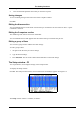
The OSD functions Scanning Computers – F4 You scan computers from the Select Computer window. To start scanning: Press F4. During scanning a Confirmation label appears, showing which Remote computer is presently displayed. See Figure 2-5. Figure 2-5 The Scan Confirmation label Note! The scan will skip any active computer set to 000 in the SCN column. To stop scanning press F4. Image tuning - F5 You can tune the image of any remote computer screen from the Select Computer window.
The OSD functions Skipping out unconnected or switched off computers- F6 When navigating through the list of computers, you can skip out the unconnected or switched off computers. You do this with Autoskip. By default, Autoskip is activated. To activate or deactivate Autoskip: In the Setup window (F3), press F6. The F6 Autoskip in the hotkey section of the OSD changes from ON to OFF When Autoskip is inactive and the computer being scanned is switched off, then the Manager screen appears dark.
Password protecting the OSD & Auto numbering Chapter 3: Passw ord protecting the OSD & Auto numbering The Management OSD comes with an advanced password security system that contains 3 different security levels. Each security level has different access rights to the system.
Enabling password protection Enabling password protection By default, password protection is disabled. To enable password protection: 1. From the Management OSD Select Computer window press F7. The Password box appears. See Figure 3-1. Figure 3-1 The Enter Password box 2. Type the default password “admin”. (You can change this password when customizing the security system). 3. Press Enter. The Password window appears. See Figure 3-2. Figure 3-2 The Password window 4. Press F7.
Password protecting the OSD & Auto numbering Setting up a password The Administrator sets up passwords for each User Profile in the Password window. See Figure 3-3. He can also edit the names to give each Profile a more identifiable name. Figure 3-3 The Password window To set up a password: 1. From the OSD Select Computer window press F7. The Enter Password box appears. 2. Type the Administrator’s password. 3. Press Enter. The Password window appears. See Figure 3-3.
Accessing the OSD using a password The 6 User Profiles Figure 3-4 The Setup window To set the User Profiles access levels: 1. Navigate to the desired User Profile and computer. 2. Change the desired access level by pressing the Spacebar. 3. Repeat steps 1 and 2 for each User Profile and computer. 4. Press Esc to save the changes. When a User accesses the system with their password they see the access levels for each computer displayed on the OSD. See Figure 3-5.
Password protecting the OSD & Auto numbering Timeout When password protection is activated you can automatically disable the Management keyboard, mouse and screen after a preset time of non-use. You set the Timeout period in the OUT column of the Setup window (F3). By default the OUT column is set to 999, which means that the Time Out function is disabled. To set Timeout: 1. From the Select Computer window press F3. The Setup window appears. 2.
Auto numbering – F12 Auto numbering – F12 Auto numbering gives each Phantom Remote a sequential ID number. Auto numbering is done through the Management OSD. For Auto numbering to work properly ALL connected computers MUST be switched on To perform Auto numbering: 1. From the OSD Select computer window Press F7. The Enter Password box appears. See Figure 3-8. Figure 3-8 The Enter Password box 2. Type the Administrators password (default password is ADMIN) and press Enter. The Password window appears.
Operating the Phantom system with the Control software Chapter 4: Operating the Phantom system w ith the Control softw are As an alternative to the OSD you can operate the Phantom system with the Control software located on the Marketing & Documentation CD. With the OSD you operate the system and view the computer screens on the same monitor. The Control software requires 2 monitors 1 for the software and 1 to view the computer screens.
The View menu P110 SD Computer screens appear here Shielded CAT5 FTP cable To System Out port USER POWER COMPUTER SYSTEM SERVICE www.minicom.com 85-265VAC 50/60 Hz To Phantom Remote System In port To Service connector RS232 Serial cable Control software installed here To computer’s Serial port Figure 4-1 The UPM with the RS232 Serial cable Installing and running the Control software Note! The Phantom system must be fully connected BEFORE running the Control software.
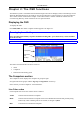
Operating the Phantom system with the Control software Selecting a Com port During the Setup process you will be prompted to choose a Com port. Choose the Com port to which the RS232 Serial cable is connected. Failure to select the correct Com port will result in the software running in demo mode. Once Setup is complete the Control window appears. See the figure below.
The View menu Communication Error If a Communication Error box appears when trying to scan the system – see Figure 4-3. Figure 4-3 Communication Error Check that: • The RS232 Serial cable is connected to the computer’s and Phantom Manager’s serial ports. • The Com Port settings in Options / Com Port are set correctly. After changing the Com port exit and re-enter the Control software. The View menu From the View menu choose to display: • All computers, or only active switched on computers.
Operating the Phantom system with the Control software The toolbar buttons Get Status If for whatever reason there is a break in communication between the Control software and the Phantom system, click to get the current status of the computers in system. The system automatically updates the status before every switching. Read Configuration To see the current settings of the entire Phantom system (names, scan settings etc.) click . All current settings are received.
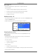
The toolbar buttons Logo and Passwords You can edit the logo that appears at the top of the OSD window. You can also edit the names and passwords for the Administrator, Supervisor and 6 Users. 1. Edit the Logo and Passwords by choosing them from the Edit menu. See figures below. Figure 4-4 The logo 2. Make the desired changes. 3. Click OK. Figure 4-5 The names and passwords Settings Choose Settings from the Edit menu. The Computers’ Properties box appears. See Figure 4-6.
Operating the Phantom system with the Control software Single computer settings To see all the settings of a single computer right click on the computer icon. The settings appear as in the figure below. Note! There is no Select box to check. Figure 4-7 The single computer Settings box Loading a saved configuration To load a saved configuration: From the File menu choose Open. The factory default settings To view to the factory default settings: From the File menu choose New.
Password protection User (Status U) – Lowest There are 6 different Users in the Phantom system. Each User has a Profile that defines the access level to different computers. There are 3 different access levels. These are: • Y – Full access to a particular computer • V –Viewing access only, to a particular computer (No keyboard/mouse functionality) • N – No access to a particular computer The Administrator defines the desired access levels of each User Profile. This is done in the Setting box.
Renumbering the Phantom Remotes Chapter 5: Renumbering the Phantom Remotes When the Phantom system was first installed, ID numbers were assigned with the auto-numbering process. Auto numbering gives each Phantom Remote a sequential number according to its physical location in the daisy chain. Remote units can be renumbered according to their physical location or by manually choosing the numbers you desire. Renumbering is done using Phantom Numbering software.
Scanning the system Selecting a Com port 1. From the Options menu, select Com port. The Com port no. box appears. 2. Choose the Com port to which the RS232 Serial cable is connected. 3. Click OK. Legend The color-coded computer icons are explained in the table below. Icon Meaning Manager. The ID number is fixed at 01. New Remote. Has no ID number at present. Existing Remote. Has an ID number. Remote with ID number set with dipswitches.
Renumbering the Phantom Remotes Auto numbering Auto numbering fills in any blank ID number boxes with the first available free ID number. To perform Auto numbering: 1. 2. In the toolbar, click Auto Numbering. All blank boxes are filled in. Click Apply. The process activates. When finished new ID numbers are assigned to the Remotes. The icons change to green. Default numbering Default numbering assigns ID numbers according to the physical location of each Remote. To perform Default numbering: 1.
Remote with dipswitches Remote with dipswitches When adding a Remote with dipswitches to the system, check that it does not have an ID number that is already in use. If it does, then when performing the scan, a Configuration Error box appears. See Figure 5-5. Figure 5-5 Configuration error To rectify this: Either change the ID number of the Remote with dipswitches. Or Use the Phantom Numbering software to adjust the ID number of the identically numbered Remote.
Renumbering the Phantom Remotes Fail icons When after a carrying out a numbering procedure, Fail icons appear – see Figure 5-7. Wait 30 seconds and repeat the numbering procedure.
Upgrading the Phantom firmware Chapter 6: Upgrading the Phantom firmw are With the Phantom Update software program you can upgrade the firmware for the: • OSD • Manager • Remote Phantom Update enables you to add new features and fix bugs in a quick and efficient manner. You can install Phantom Update on the Manager computer or any other computer, even one not part of the Phantom system. The Phantom Update software and firmware is on the Marketing & Documentation CD.
Starting and Configuring Phantom Update Starting and Configuring Phantom Update 1. Start the Phantom Update software. The Phantom Update window appears. See Figure 6-1. Manager box Remote computers Status box Figure 6-1 The Phantom Update window The table below explains the functions of the buttons and boxes in the Phantom Update window.
Upgrading the Phantom firmware Displaying the maximum number of Remote units Select the maximum number of Remote units to display in the Phantom Update window. By default 64 Remote units are displayed. 1. From the Options menu choose Remotes. The Remotes box appears see Figure 6-3. 2. Select the maximum number of Remote units in your Phantom system. 3. Click OK.
Verifying the Remote version number Manager box Figure 6-5 The OSD Manager option The H/W Version button is grayed out, as there is no hardware relevant to the OSD. The Phantom Manager version number To verify the Phantom Manager version number: 1. Open the Phantom Update program. 2. Activate the Firmware Upgrade mode on the Manager OSD. 3. In the Manager Unit box, check the Phantom Manager option. 4. Click . The firmware version number appears in the Manager Unit box. 5. Click .
Upgrading the Phantom firmware Updating the firmware Warning! Never switch off any computer connected to the Phantom system during the updating process. To update the firmware: 1. Open the Phantom Update program. 2. Activate the Firmware Upgrade mode on the Manager OSD. 3. In the Phantom Update window, check the appropriate option in the Manager Unit box or the desired remote computer or computers. 4. From the File menu, choose Open. The Open box appears. See Figure 6-6. 5.
Wrong firmware Wrong firmware When the firmware you are trying to flash is incompatible with the Phantom units a Not Compatible message appears stating that some or all units are not compatible with the selected firmware. Figure 6-7 The Not Compatible message In this case go to http://www.minicom.com/phandl.htm for information on how to correctly identify Phantom units. All new Phantom units are protected from being updated with the wrong firmware.
Upgrading the Phantom firmware Electricity failure When the electricity fails while updating the Phantom firmware, do the following: If the electricity fails during the firmware update of the Manager, a Communication Error message appears. The Phantom Manager enters the Upgrade mode automatically without displaying the Firmware Upgrade label. Simply resume the firmware update by opening the folder that contains the firmware update file and continue from there.
Phantom Specter USB SUN Combo keys Appendix A: Phantom Specter USB SUN Combo keys The SUN keyboard consists of a special keypad to perform special functions in the SUN Operating System environment. A PS/2 keyboard connected to the Phantom Manager does not have a corresponding keypad, so the Phantom USB emulates these keys using a set of key combinations called Combo keys. See the table below.