Smart 116 IP User Guide w w w . m i n i c o m . c o m International HQ North American HQ European HQ Jerusalem, Israel Linden, NJ, USA Dübendorf, Switzerland Tel: + 972 2 535 9666 minicom@minicom.com Tel: + 1 908 486 2100 info.usa@minicom.com Tel: + 41 44 823 8000 info.europe@minicom.com Technical support - support@minicom.
SMART 116 IP Table of Contents 1. Welcome ...................................................................................................................... 4 Section I ........................................................................................... 5 2. Introduction ................................................................................................................. 5 3. Key features ...............................................................................................
USER GUIDE 22. Logging out ............................................................................................................. 22 23. Starting a remote session ....................................................................................... 23 23.1 Taking over a busy remote session................................................................................................ 24 23.2 Full screen mode...........................................................................................
SMART 116 IP 27.5 Starting and configuring the Update software................................................................................ 47 27.6 Verifying the version numbers ........................................................................................................ 49 27.6.1 116 IP Switch version ............................................................................................................. 49 27.6.2 RoC/RICC version number...................................................
USER GUIDE 1. Welcome Thank you for buying the Smart 116 IP system. This system is produced by Minicom Advanced Systems Limited. This document provides installation and operation instructions for Minicom’s Smart 116 IP. It is intended for system administrators and network managers, and assumes that readers have a general understanding of networks, hardware and software.
SMART 116 IP Section I This section explains how to configure and operate the Smart 116 IP system remotely over IP. Section II on page 36, explains how to operate the Smart 16 IP Switching system locally through the On Screen Display (OSD). 2. Introduction The Smart 116 IP extends your KVM (keyboard, video, mouse) from any computer or server over TCP/IP via LAN, WAN or Internet connection.
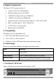
USER GUIDE 4. System components The Smart 116 IP system consists of: · 1 Smart 116 IP (p/n 1SU60005/R) · Rack mounting set (p/n 5AC20247) · 1 RS232 Download cable (p/n 5CB40419) · 1 RS232 Cross cable (p/n 5CB00566) · Remote Interface Connection cables (RICCs) – PS/2, SUN, USB · RICC on Cable (RoCs) - PS/2, USB (SUN) · CAT5 cables (1.5m provided) · Rack mounts for the RICCs 5.
SMART 116 IP 7.1 LED and button table LED Function Power Power Indicator Remote Illuminates when remote session is active Link Unit is connected to the system Button Function Local When pressed, Smart 116 IP disconnects the Client computer’s link to the Target Server and the local mouse and keyboard become operational. The Remote LED turns off.
USER GUIDE · Place the Smart 116 IP on a flat, clean and dry surface · The Smart 116 IP is not intended for connection to exposed outdoor lines · Ensure that the maximum distance between each computer and the Smart 116 IP, does not exceed 10m/33ft 8.1 Avoiding general rack mounting problems Elevated operating ambient temperature The operating ambient temperature of the rack environment may be greater than the room ambient when installing into a closed or multi-unit rack assembly.
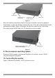
SMART 116 IP Front of unit Position here for front facing Position here for rear facing Rear of unit Figure 3 Place the brackets towards the front of the unit so that the unit can be mounted front facing, or place the brackets towards the rear of the unit so that the unit can be mounted rear facing. Figure 4 illustrates the bracket connected for rear facing. Screw the bracket to the Smart 116 IP using the screws provided. Bracket connected for rear facing rack mounting Rear of unit Figure 4 9.
USER GUIDE I 0 SERIAL 9 10 11 12 13 14 15 16 L AN 1 2 3 4 5 6 7 8 CONSOLE POWER 100-240 VAC 50/60 Hz FL ASH To LAN port h p w o rk s t a ti o n b 2 6 0 0 User over IP To servers M I NI C OM h p w o rk s t a ti o n b 2 6 0 0 Internet / VPN / LAN M IN I C OM h p w o rk s t a ti o n b 2 6 0 0 RoC/RICCs h p w o rk s t a ti o n b 2 6 0 0 h p w o rk s t a ti o n b 2 6 0 0 h p w o rk s t a ti o n b 2 6 0 0 h p w o rk s t a ti o n b 2 6 0 0 Figure 5 Smart 116 IP system overview
SMART 116 IP To computer’s Video Card To computer’s USB Port Figure 7 RoC USB (SUN) 10.2.1 Connecting a RoC/RICC PS/2 The connections for RoC/RICC PS/2 are exactly the same. Figure 8 illustrates the RICC PS/2. You can connect the RoC/RICC PS/2 to a powered on computer, but it must be in the following order: 1. Connect the Mouse connector to the computer’s Mouse port. 2. Connect the Keyboard connector to the computer’s Keyboard port. 3. Connect the Screen connector to the computer’s Video port.
USER GUIDE 10.2.2 Connecting a RoC/RICC USB The RoC/RICC USB supports Windows 98 SE and later, MAC, SUN and SGI, and all modern Linux distributions. The connections for RoC/RICC USB are exactly the same. Figure 9 illustrates the RICC USB and its connections. To connect the RoC/RICC USB: 1. Connect the Screen connector to the computer’s Video port. 2. Connect the USB connector to the computer’s USB port. To Video Card To USB Port RICC USB CAT5 cable to Smart 116 IP Server port Figure 9 RICC USB 10.2.
SMART 116 IP 10.3 Connecting the CAT5 cables 1. Connect one connector to the RoC/RICCs RJ45 port. 2. Connect the other connector to one of the Smart 116 IP’s Computer ports. 3. Follow the above 2 steps for each computer. 10.4 Connecting a KVM console To operate the system locally, connect a KVM console to the Smart 116 IP: 1. Connect the monitor’s connector to the Smart 116 IP’s Monitor port. 2. Connect the keyboard’s connector to the Smart 116 IP’s Keyboard port. 3.
USER GUIDE Connect the Smart 116 IP units one at a time and change the static IP address of each unit before connecting the next unit. 12. Logging into the Web interface Complete the initial setup via the Web configuration interface: 1. Open your Web browser (Internet Explorer version 6.0 or higher). 2. Type the Smart 116 IP system IP address - https://IP address/config - and press Enter. The login page appears, see Figure 11. Figure 11 Login page 3.
SMART 116 IP 12.1 SSL Certificate notes When first connecting to Smart 116 IP’s https configuration page, 2 browser security warnings appear. Click Yes to proceed. The first warning disappears upon first Smart 116 IP client installation, when Minicom’s root certificate is installed. 13. Network > Configuration Consult your Network Administrator for the network settings. Device name - Type a name for the Smart 116 IP. Default device name consists of the letter ‘D’ followed by the 6-digit device number (D.
USER GUIDE requirements. It is the most comprehensive remote server maintenance solution available in the market today. Enable KVM.net - Check this option to allow Smart 116 IP unit to be remotely managed by Minicom’s KVM.net system. Manager Auto Discovery – when checked, KVM.net automatically detects the Smart 116 IP, if it resides on the same network segment. Manager IP – If Smart 116 IP resides on a different segment, type the static IP address of the Smart 116 IP. 14.
SMART 116 IP Administrator An Administrator has unrestricted access to all windows and settings and can “take over” any active session (explained in section 23.1 on page 24). An Administrator can change the name and password and Target server permissions of all users. User A User can access/control Target Servers, but cannot use the advanced mouse settings. A User has no access to the Web configuration interface.
USER GUIDE 15.3 Deleting a user To delete a user: 1. Select the user from the list. 2. Click . 3. Click , the changes are saved. 15.4 Blocking a user An alternative to deleting a user is blocking a user. This means that the user’s name and password is stored, but the user is unable to access the system. Check Block to block a user. Uncheck Block to allow the user access. 16.
SMART 116 IP Install switch definition file In the event that Minicom’s Technical Support updates the Switch Definition file, the file will be available in the Support section of our website www.minicom.com. 1. Load the file onto the Client computer. 2. Locate and install the Switch Definition file. The switch definition file is replaced. 17. Administration > User Targets By default access is denied to all servers for all user types including Administrators.
USER GUIDE 18. Security > Settings Configure the security features, such as Account Blocking, Password Policy and Idle Timeout, as explained below. From the Security section click Settings, the Security Settings appear, see Figure 16. Figure 16 Security Settings The Security Settings fields: Account Blocking – decide on the number of attempts to login with a wrong username or password after which there is a time lock or a total block.
SMART 116 IP 19. Security > SSL Certificate You can install an SSL certificate. To do so: From the menu, select SSL Certificate, the install SSL Certificate page appears, see Figure 17. Figure 17 Install SSL Certificate page Certificate File - Browse to locate the cer file. Private File - Browse to locate the private key file. Key Password - Type the “private key” password. Click . 20. Maintenance > Firmware Upgrade Upgrade the Smart 116 IP firmware to take advantage of new features.
USER GUIDE Note! Depending on the type of firmware upgrade, the following settings may be erased: User settings, server names, mouse and video adjustments. For more information refer to the firmware release notes. The network settings remain intact. 21. Restore Factory Settings You can restore the Smart 116 IP unit to the factory settings.
SMART 116 IP 23. Starting a remote session At a Client computer open Internet Explorer (6.0 and above) and type the Smart 116 IP’s IP address. https://IP address. (Note! Only SSL connections are allowed, therefore type HTTPS before the IP address or the name of the Smart 116 IP). The Login page appears. Type your username and password and press Enter. By default, the user name is: admin and the password is access, (both lower case). On first connection install the Minicom certificate and ActiveX control.
USER GUIDE Minicom icon – Hold the mouse over the icon to view information about current server, connection time and video mode. 23.1 Taking over a busy remote session While only one user can have control, many users can be connected simultaneously. When connecting to a busy Target Server an Administrator has the option to take over the Target Server. A User only has this option when the current session is run by another User, but not by an Administrator.
SMART 116 IP 23.3 The Toolbar To maximize the Toolbar: Click the arrow . Click again to minimize the Toolbar. When maximized, the Toolbar can be dragged and dropped to anywhere on the screen, by dragging the icon screen. . When minimized the icon glides to a side of the To hide the Toolbar, either: Double-click the Smart 116 IP System tray icon . Or Press F9. To display the Toolbar repeat the above action. See also page 33. 23.
USER GUIDE Figure 22 Settings.. Dialog box Bandwidth Choose from the following options Adaptive – automatically adapts to the best compression and colors according to the network conditions. (Not recommended because network parameters may change frequently impacting on user experience). Low - Select Low for high compression and 16 colors. Medium - Select medium for medium compression and 256 colors. Medium is recommended when using a standard internet connection.
SMART 116 IP 23.6.1 Refresh Select Refresh or press Ctrl+R to refresh the Video image. Refresh may be needed when changing the display attributes of a Target Server. 23.6.2 Manual Video Adjust Use the manual video adjustment for fine-tuning the Target Server video settings after auto adjustment or for adapting to a noisy environment or a non-standard VGA signal or when in full-screen DOS/CLI mode. To adjust the video manually: Click Manual Video Adjust. The manual controls appear, see Figure 23.
USER GUIDE Select Filter - defines the filter of the input video from the server. A higher filter reduces the noise level but makes the image heavier. Noise Level - represents the Video "noise" when a static screen is displayed. 23.6.3 Auto Video Adjust To adjust the video automatically: Click Auto Video Adjust. The process takes a few seconds. If the process runs for more than 3 times, there is an abnormal noise level.
SMART 116 IP 1. Click Add Predefined. A list of sequences appears. 2. Select the desired sequence and click OK. The sequence appears in the Special Key Manager box. 3. Click OK. The sequence appears in the Keyboard Key sequence list. To record a key sequence: 1. From the Special Key Manager box press Record New. The Add Special Key Dialog box appears, see Figure 25. Figure 25 Add Special Key Dialog box 2. Give the key sequence a name in the Label field. 3. Click Start Recording. 4.
USER GUIDE 23.9 Synchronizing mouse pointers When working at the Client computer, two mouse pointers appear: The Client computer’s is on top of the Target Server’s. The mouse pointers should be synchronized. The following explains what to do if they are not synchronized. Warning Before synchronizing mouse pointers adjust the video of the Target Server, (explained above) otherwise mouse synchronization may not work. 23.9.
SMART 116 IP 1. From the Toolbar click box appears see Figure 26. / Manual Settings. The Mouse Settings Dialog Figure 26 Mouse Settings Dialog box 2. Select the Target Server’s Operating System and click OK. Instructions and sliders appear. 3. Follow the instructions and set any relevant sliders to the same values as set in the Target Server’s Mouse Properties window. 2 examples! For Windows XP, 2003 Server, Vista and Longhorn Server.
USER GUIDE Figure 27 Mouse Emulation Dialog box Select the mouse connected to the Local Console port on the Smart 116 IP, e.g. if the local mouse is a 2 button mouse, select Standard Mouse. Switch Acceleration - This setting should NOT be changed. Max Rate - this defines the maximum mouse report rate. For Sun Solaris the default value is 20 in order to support older Sun versions. 23.10 Minicom icon menu features , a menu appears.
SMART 116 IP Full Screen Mode - Check this option to make the remote session screen appear in full screen mode from the next reconnection onwards. To toggle the full screen mode on and off, press F11. Configuration – This only appears in the menu when an Administrator is logged in. Click Configuration to access the Web configuration interface. 23.11 Disconnecting the remote session . The Login page appears.
USER GUIDE Figure 29 Login page 4. Type username: admin , password: SAFEmode. (Case sensitive). (This username and password works only in Safe mode). A menu appears, see Figure 30. Figure 30 Safe mode menu 24.2 Restoring factory defaults To restore factory defaults: 1. From the menu choose Restore Factory Settings. A warning appears see Figure 31. Figure 31 Warning 2. Click . A further warning appears, see below.
SMART 116 IP Figure 32 Warning 3. Click OK, the factory defaults are restored. When the process finishes Figure 33 appears. Figure 33 Reboot 4. Click Reboot to restart the unit. 24.3 Restoring the device firmware Contact Minicom Technical Support support@minicom.com, to receive the Upgrade firmware required to restore the device firmware. Save the Upgrade firmware on the hard disk of a computer connected to the network. To restore the device firmware: 1. From the Safe mode menu choose Firmware Upgrade.
USER GUIDE Section II Section II explains how to operate the Smart 116 IP Switching system locally (sections 25 and 26) and how to upgrade the Smart 116 IP firmware (section 27). Section 28 deals with troubleshooting. 25. Switching between computers Switch between the connected computers by either: · Keyboard hotkeys · The OSD (On Screen Display) 25.1 The keyboard hotkeys To switch to the next computer forwards press Shift then, +. Release Shift, before pressing +.
SMART 116 IP 26.1 Navigating the OSD To navigate up and down use the Up and Down arrow keys. To jump from one column to the next (when relevant) use the Tab key. To exit the OSD or return to a previous window within the OSD press Esc. 26.2 Selecting a computer To select a computer: 1. Navigate to the desired computer line. Or, type the port number of the desired computer. 2. Press Enter. The selected computer is accessed. A Confirmation label appears showing which computer is accessed.
USER GUIDE Figure 37 General Settings window From this window you can do the following: 26.3.1.1 Security The OSD comes with an advanced password security system that contains 3 different security levels. Each security level has different access rights to the system.
SMART 116 IP 26.3.1.2 Activating password protection By default OSD access is not password protected. Only the Administrator can password-protect the OSD or disable password protection. To do so: 1. In the General settings window navigate to the Security line. 2. Press the Space bar to toggle between Security On and Off. The password box appears. 3. Type the Administrator’s password (default is “admin”). 4. Press Enter. The new security status is set. 26.3.1.
USER GUIDE 1. Navigate to the Keyboard language line. 2. Toggle between the options using the Space bar. 26.3.1.7 Editing the Switch name You can substitute up to 18 characters in the line. A space constitutes a character. When there is more than one switch in the system give each Switch’s OSD a different name. 26.4 F7 Defaults Press F7 to return the OSD to the factory default settings. Note! All changes made will be erased. 26.
SMART 116 IP 26.5.2 Keyboard (KB) The Smart 116 IP operates with Windows, Linux, HP UX, Alpha UNIX SGI, DOS, Novell, MAC-USB or Open VMS. By default the keyboard mode is set to PS for Intel based computers. For the other systems set the KB column as follows: · U1 for HP UX · U2 for Alpha UNIX, SGI, Open VMS · U3 for IBM AIX To change the setting: 1. On the desired line, press Tab to jump to the KB column. 2. Toggle between the options using the Space bar. 26.5.
USER GUIDE Figure 39 Time settings window 26.6.1 Scan (SCN) - Label (LBL) - Time out (T/O) SCN - In the SCN column, change the scan period. LBL - In the LBL column, change the display period of the Confirmation label showing which computer is currently accessed. T/O - When password protection is activated you can automatically disable the Management keyboard, mouse and screen after a preset time of non-use. Set this Timeout period in the T/O column. To set the above periods: 1.
SMART 116 IP Figure 40 Users settings window There are 3 different access levels. These are: · Y – Full access to a particular computer. · V –Viewing access only, to a particular computer (No keyboard/mouse functionality) · N – No access to a particular computer – A TIMEOUT label appears if access is attempted To give each user the desired access level: 1. Navigate to the desired computer line and User column. 2. Toggle between the options using the Space bar. 26.
USER GUIDE Figure 41 Security settings window The ‘T’ column on the right hand side stands for Type of access permission. There can only be 1 Administrator password, 1 Supervisor password, and 6 User passwords. To change a user name or password: 1. Navigate to the desired line and column. 2. Type a new user name / password. User authentication is done solely via the password there is no security significance to the names. By default the User Profile settings are full access. 26.
SMART 116 IP Please note! All the functions set out in the Help window are performed from the Main window. The Help window is merely a reminder of the hotkeys and their functions. 26.10 Scanning computers – F4 Where necessary adjust the scan time in the Time Settings window, see above. To activate scanning: 1. Press Shift twice to open the OSD. 2. Press F4. Your screen displays each active computer sequentially, with the Scan label appearing in the top left corner. To deactivate scanning: Press F4. 26.
USER GUIDE 27. Upgrading the Smart 116 IP firmware With the Smart 116 IP Switch Update software you can upgrade the firmware for the: · Switch processors · RoC/RICCs The Update software enables you to add new features and fix bugs in a quick and efficient manner. Install the Update software on any computer, even one not part of the Smart 116 IP system. The software can be downloaded from the Support section at www.minicom.com, it is also on the supplied CD.
SMART 116 IP I 0 SERIAL 9 10 11 12 13 14 15 16 LAN 1 2 3 4 5 6 7 8 CONSOLE POWER 100-240 VAC 50/60 Hz FLASH To Flash connector RS232 Download cable MI N ICO M Update software installed here MIN I CO M RoC/RICCs to servers Figure 43 RS232 cable 27.4 Installing the software To install the Update software: 1. Download the software from the Support section of Minicom’s website, or locate it on the supplied CD. 2. Install the software on the computer’s hard drive. 27.
USER GUIDE Smart 116 IP Switch RoC / RICCs Status bar Figure 44 Smart 116 IP Switch Update window The table below explains the functions of the buttons and boxes in the Update window. Button or Box Function Selects all RoC/RICCs Unselects selected RoC/RICCs Starts firmware download Displays the firmware version numbers Displays the hardware version numbers Cancels selected function System time Displays download status Name of Update file 2.
SMART 116 IP Figure 45 Com Port Dialog box 3. Choose the Com Port the RS232 Serial cable is connected to and click OK. 27.6 Verifying the version numbers Before upgrading the firmware, you must first verify which firmware and hardware versions you have. 27.6.1 116 IP Switch version To verify the Smart 116 IP Switch version: 1. Select the 116 IP Switch checkbox. 2. . The firmware versions of the Translator, Master and Click OSD appear, see Figure 46. Figure 46 Firmware version report 3.
USER GUIDE Figure 47 Hardware version report 27.6.2 RoC/RICC version number Before you can tick a RoC/RICC, you must unselect the 116 IP Switch checkbox. To verify the RoC/RICC version number: 1. Check one or more or all of the RoC/RICCs. 2. Click . The firmware version number appears. 3. Click . The hardware version number appears. When “Not responding” appears, there is no computer connected, or it is switched off. 27.
SMART 116 IP Figure 48 Open box 4. Open the file. 5. Click Start. The Smart 116 IP Switch Update flashes the firmware. On completion the firmware version number appears. 6. Check that the updated version number is correct by pressing . Firmware Update generates one log file per session that displays a chronological list of actions. You can read the log file in any ASCII text editor. The log file is located in the Windows directory. 28.
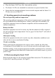
USER GUIDE 2. Select Options/Advanced/Reset. The unit resets. The system should now be operational. 28.2 Setting default values for the OSD To return the OSD to the factory default settings: Select Options/Advanced/Set Default. A warning appears, click OK. The OSD returns to the factory default settings. 28.3 Get Status If there is a break in communication between the Update software and the system, select Options/Get Status to get the current status of the computers in system. 28.
SMART 116 IP 29. Technical specifications Operating systems Target Server Windows, Linux, UNIX and other major operating systems Client Computer Windows 2000 or higher with IE 6.
USER GUIDE 30. Video resolution and refresh rates Hz → 56 640x480 60 65 x 66 70 72 x x x x x x x x 720x400 800x600 1024x768 73 75 76 x x x x x 85 86 x x 1152x864 x x x x x x 1152x900 x 1280x720 x 1280x768 x 1280x960 x 1280x1024 x 1600x1200 x x x x x x x x x x x x 31. Safety The device must only be opened by an authorized Minicom technician. Disconnect device from AC mains before service operation! 32.
SERIAL REMOTE POWER SWITCH Regional Offices Germany France Italy Kiel Vincennes Rome Tel: + 49 431 668 7933 info.germany@minicom.com Tel: + 33 1 49 57 00 00 info.france@minicom.com Tel: + 39 06 8209 7902 info.italy@minicom.com England Camberley Tel: + 44 (0) 1276 25053 info.uk@minicom.com www.minicom.