AccessIT User Guide w w w . m i n i c o m . c o m International HQ America Jerusalem, Israel Linden, NJ, USA Tel: + 972 2 535 9666 minicom@minicom.com Tel: + 1 908 486 2100 info.usa@minicom.com Technical support - support@minicom.
USER GUIDE About this User Guide This User Guide provides installation and operation instructions for the AccessIT Manager system produced by Minicom Advanced Systems. It is intended for system administrators and network managers, and assumes that readers have general understanding of networks, LDAP, hardware and software. All information in this User Guide is subject to change without prior notice. User Guide Feedback Your feedback is very important to help us improve our documentation.
AccessIT Table of Contents 1. Introduction ......................................................................................................... 7 1.1 Key features ...............................................................................................................7 1.2 System components..................................................................................................8 1.3 Terminology .............................................................................................
USER GUIDE 7.1.2 Minicom KVM/IP .................................................................................................31 7.2 PDUs tab...................................................................................................................33 7.3 Target Sets tab.........................................................................................................34 7.4 Access Permissions tab..........................................................................................34 7.
AccessIT 10.3.8 VNC ..................................................................................................................62 10.3.9 Telnet................................................................................................................63 10.3.10 VMware Server...............................................................................................64 10.3.11 New Access Services .....................................................................................65 11.
USER GUIDE 15.2.2 Resetting AccessIT configuration .....................................................................96 15.3 Firmware upgrade..................................................................................................97 15.3.1 Upgrading the IP devices firmware...................................................................97 15.3.2 Upgrading the AccessIT Manager ....................................................................97 15.4 Replication ..............................
AccessIT 17.9.3 Advanced........................................................................................................116 17.10 Power cycle ........................................................................................................117 17.11 Keyboard key sequences..................................................................................117 17.12 Synchronizing mouse pointers.........................................................................119 17.12.
USER GUIDE 1. Introduction AccessIT is an appliance based application that provides IT staff with secure and centralized management of all remote access services in the organization. It operates in both Windows and Linux environments and is accessible from Internet Explorer and Firefox. AccessIT is a web-based management solution that consolidates in-band and outof-band remote access services onto one user-friendly web portal.
AccessIT Virtual Media - Virtual Media is a very useful tool for those who need to manage large numbers of computers such as commercial IT data center managers. A Target computer can be made to boot to one of many virtual disks that can perform any variety of tasks such as virus scans of the Target’s physical drive or patch management or even complete installation of the operating system on a Target computer. 1.
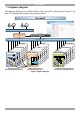
USER GUIDE 1.4 System diagram The diagram below gives a brief outline of the AccessIT system setup. Section 3 on page 12 explains the system setup in more detail. AccessIT AccessIT Manager Users login to AccessIT and choose their preferred method of accessing their server KVM.ne t PowerEdge 1 95 0 LAN / WAN / VPN DXUIP II Smart 216/32IP HP ILO VMware Server SSH Telnet VNC SmartRack 116IP Smart 116 IP PX IP Control Power Go Local 3.3 V/2 A Se ri al Remote Desktop Virtual Machines Power Distr.
AccessIT 2. Pre-installation guidelines Prepare a list of all AccessIT system components. You will need this information to configure the system. Appendix A on page 134 contains 2 lists of the details you need to prepare for Minicom KVM/IP devices and PX units (not PX Serial). Photocopy or print out Appendix A. For other access services see section 2.1 below. The lists should include the IP device name and MAC address, KVM switch and the Target details.
USER GUIDE 2.1 Access services details Besides the Minicom KVM/IP devices mentioned above, you can connect to Targets via the following Access services through AccessIT: · Minicom’s PX Serial · Web · ILO · RDP · SSH · VNC · Telnet · VMware Server These services are elaborated on in the section 3.6. All service applications must be installed on the local (client) computers. See section 10.3 on page 55 which sets out the details required for each of the above Access service. 2.1.
AccessIT 3. Understanding the system – an overview The figure below shows a typical AccessIT application. Figure 3 AccessIT typical application The system works as follows: Data centers in locations throughout the world are connected to Minicom IP devices and to other 3rd party access services. The Minicom IP devices are Centralized Management enabled allowing AccessIT to access/control the Targets connected to all IP devices via IP.
USER GUIDE 3.1 Creating users An Administrator can create users with 2 different possible permission types: · Administrator · User These permission types are explained fully in section 6. In the example below 4 users are created with various permission types.
AccessIT Target servers Dell #1 Dell #2 Dell #3 Dell #4 Figure 6 Created Targets 3.4 Forming Targets into sets Targets can be formed into sets. You can for example create a set of all financial servers. In the example below 3 Targets are formed into Target Set - Finance. Target servers Dell #1 Dell #2 Dell #3 Dell #4 Target Set - Finance Dell #1 Dell #2 Dell #3 Figure 7 Forming Targets into sets 3.
USER GUIDE This means that: · The Finance Group has access rights to Target Set - Finance. · Any user added to the Finance Group will automatically have access rights to Target Set - Finance. Note! Users can be members of many different groups. In the example below Sid belongs to the Finance Group and also to the Marketing Group.
AccessIT Besides the Minicom KVM/IP devices, you can connect to Targets via the following Access services through AccessIT: · · Minicom’s PX Serial - PX Serial is a one-port RS232/422/485 to Redundant Ethernet device server. Web – Browser based web service · ILO - HP Integrated Lights-Out (iLO). HP ILO gives seamless access to HP servers. · RDP - Remote Desktop Protocol. RDP is a multi-channel protocol that allows a user to connect to a computer running Microsoft Terminal Services.
USER GUIDE 4. Setting up the system Set up the Minicom IP device systems according to their User Guide instructions. In order to be managed by AccessIT, all Minicom IP devices must be configured to be Centralized Management enabled. This is done from the Network Configuration page of each IP device. For example, see the Centralized Management section in Figure 10, Centralized Management is enabled by selecting the Enable Centralized Management checkbox.
AccessIT 4.2 AccessIT Manager’s default IP address Each AccessIT Manager unit comes with the following default values: IP address - 192.168.1.250. Subnet mask - 255.255.255.0 Gateway - 192.168.1.1 If these values are not suitable for your network, follow the steps in the section below to display the AccessIT interface. You can then change the IP address of the AccessIT Manager in the Network tab under Settings/Unit Maintenance, see section 16.2 on page 106. 4.2.
USER GUIDE 5. Displaying the AccessIT web interface To display the Web interface: 1. Open your Web browser (Internet Explorer version 6.0 or Firefox 3 or higher) versions. 2. Type in the IP address of the AccessIT Manager (default IP address https://192.168.1.250) and press Enter. Note! The IP address must begin with https:// and not http://. The Login page appears. Bookmark it for easy reference. 3. Type the login name and password. Default username is admin and password is access. 4. Press Enter.
AccessIT Figure 12 AccessIT client 5.1 Menu section The menu section on the left, see Figure 11 is sub-divided into 3 sections: Management, which includes the configuration pages for IP devices, PDUs, Serial Console servers, Targets and Users/Groups. Access, which contains access pages to all allowed Targets and Target Groups. Settings which contains 3 configuration sections: Application, Attached Devices and Maintenance.
USER GUIDE 6. Creating users There are two possible methods of inputting users into the system. When using local authentication (see page 55) users and groups are created in the AccessIT GUI. When using an LDAP authentication server (see page 81) users and groups are imported from a Windows Active Directory.
AccessIT 2. Click . The following appears. Figure 14 New User 6.1 General tab Fill in the following details: User name - type a login name. A User name cannot be identical to any other existing User name. It can contain uppercase or lowercase characters except for the following: : ; ? & < > ” A User name cannot include spaces. Full Name - type the User’s real name Password / Retype Password - type a password. E-mail address, Phone number, Description – these are optional fields.
USER GUIDE Once selected, User Groups appear here All User Groups in the system appear here Figure 15 User Group tab 2. Select the Groups that the new User will be a member of. The Groups appear in the Member of list. 6.2.1 Removing Users from a Group To remove Users from a Group: In the All User Groups section, unselect the Group’s checkbox. The Group is removed from the Member of list. 6.3 Access Permissions tab You can choose which Targets and Target sets the user has permission to access.
AccessIT Targets and Target Sets that the new user has permission to access appear here Select from the All Targets and All Target Sets lists those which the new user will have permission to access Figure 16 Access Permissions tab The All Targets and All Target Sets lists show the Targets and All Target sets in the system. 2. Select the checkboxes of the desired Targets / Target sets. They appear in the Targets and Target Sets: list.
USER GUIDE By clicking a user name, an Administrator can access the General, User Group and Access Permissions tabs of this user and change any of the parameters. 6.4.1 Deleting a user Deleting a user, instantly removes the user’s authorization from the AccessIT system and all IP devices. To delete a user: 1. On the Users page select the checkboxes of the users to be deleted. . The user is removed. Press 2. Press deselect all checkboxes with one click. to select or 6.
AccessIT 2. Name: Type a unique name for the Group. You can add a description. 3. Select the checkboxes of the users to be part of the Group. They appear in the Group members list. You can access the User Properties page by clicking a user name in the Group members list. 6.5.1 Access Permissions tab Click the Access Permissions tab, Figure 19 appears.
USER GUIDE 6.5.2 Allowed Services tab Click the Allowed Services tab. The following appears. Figure 20 Allowed Services tab Here you assign Access Services to Group members. If a Group member has permission to access a Target, but there are no assigned Access Services for the Group, then the Group member will not be able to access the Target. Select the checkboxes of all access services allowed to this Group. 6.5.3 Saving the new Group Click . The Group’s details are now in the system.
AccessIT Icons of access services allowed appear here User Groups Figure 21 User Groups page 6.5.4 Deleting a User Group To delete a Group: 1. On the Users Group page select the checkboxes of the Groups to be deleted. 2. Press . The Groups are removed. Press deselect all checkboxes with one click. Note: Deleting a Group will not delete the individual users.
USER GUIDE 7. Configuring Targets You must input the de tails of all the Targets physically connected to the system’s IP devices / KVM switches. This includes giving each Target a unique name and other relevant details. As mentioned in the pre-installation guidelines, Appendix A on page 134 contains 2 lists of all the details you need to prepare. To configure a Target: 1. From the Management menu, select Targets the Targets page appears see Figure 22.
AccessIT · Target Sets – The Target Sets this Target is a member of. · Description - optional description of the Target. 2. From the toolbar, click Figure 23. . The New Target page appears, see Name - Type a unique name for each server in the system. Once selected access services appear here All possible access services appear here Figure 23 New Target page 7.1 Access Services tab Here you select and configure all access services relevant to this Target.
USER GUIDE 7.1.1 Default access service You can set any of the access services to be the default service. This means that the service will be used to access the Target by default when selecting the Target by clicking the Target name. To access the Target via a different service, the service must be selected. To set a service as the default, display the service as explained below and select the Set as Default Service checkbox – circled in Figure 23. 7.1.
AccessIT Figure 26 KVM/IP Device / Port number To remove an assigned Target from an IP device/ KVM switch port click . The assignment is removed. Other KVM/IP elements are as follows: Relative/Absolute mode/Apple Macintosh – Absolute Mouse mode and Apple Macintosh are only relevant for PX USB KVM/IP devices. All other KVM/IP devices must have Relative Mouse Mode selected (which is the default).
USER GUIDE 7.2 PDUs tab Where a Target is connected to a PDU, you must associate the PDU with the Target. To do so: 1. Press the PDUs tab. The following appears. PDU selected appears here All PDUs in the system appear here Figure 27 PDUs tab 2. Names of all configured PDUs appear in the All PDUs list. To configure a PDU see section 9 on page 48. From the All PDUs list, select the checkbox of the PDU the Target is connected to. The PDU appears in the Connected PDUs list with its details below this.
AccessIT Tip! Instead of assigning an individual Target to a PDU outlet, you can assign all the PDU outlets to all relevant Targets as explained in section 9.1.1 on page 49. 4. Double-click the port number row to which the Target is connected. The name of the target appears in that row. Note! You can assign the target to as many PDU ports or different PDUs as needed. 5. Click Save. The changes are saved and the New Target page reappears showing the assigned port number. 7.
USER GUIDE Select from the All Users and All Groups lists those which will have permission to access this Target Users and Groups that have permission to access this Target appear here Figure 30 Access Permissions tab All existing Users appear in the All Users list. All Groups appear in the All Groups list. To choose which Users / Groups have access to the Target: 1. Select the checkboxes of the Users or Groups. They appear in the Users and Groups: list.
AccessIT 7.7 Creating a Target Set You can group Targets into sets. E.g. make a set of all financial servers in the system. You can then give users access rights per the Target Set rather than per individual Targets. Target Sets appear as a Favorites folder for users on the Access page. To create a new Target Set: . The following appears. 1.
USER GUIDE Select from the All Users and All Groups lists those which will have permission to access this Target set Users and Groups that have permission to access this Target set appear here Figure 32 Access Permissions tab All existing Users appear in the All Users list. All Groups appear in the All Groups list. To choose which Users / Groups have access to the Target set: 1. Select the checkboxes of the Users or Groups. They appear in the Users and Groups: list.
AccessIT remove Targets from the Target set, and from the Access Permissions tab choose which Users and Groups can have access permissions to the Target set, as explained on page 36. You can access Target properties by clicking a Target name in the Assigned Targets list. Targets that are members of this Target set appear here All Targets in the system appear here Figure 34 Target set 7.7.3 Deleting a Target Set You can delete a Target set from the Target Sets page: 1.
USER GUIDE 8. Configuring KVM/IP Devices The web interface opens at the Devices page, see Figure 35. The New Devices section automatically displays all IP devices detected by the AccessIT system. (For IP devices to appear they must be configured to be Centralized Management enabled – see section 8.1 below). Each device appears identified by its MAC address. The MAC address of each IP device is written on a sticker on the unit’s underside.
AccessIT Warning – Problem with the device. See the Devices page on page 40 for more information. Uploading – Device is receiving new firmware from AccessIT Manager. Updating device – Device is receiving an updated configuration from AccessIT Manager. Rebooting - Device reboots upon any Network parameter change, or firmware upgrade. Connecting – AccessIT send or receives the Device Discovery message. Version – Displays the device firmware version number.
USER GUIDE Name - You must assign a unique name to each IP device before associating connected Targets or KVM switches. Type a name for the device. Description – These are optional fields used for device identification. Status – This is the connection status. Device Info - contains information about the device, including its operational status and version numbers of firmware, KME (keyboard, mouse emulation), hardware, SDF (switch definition file) and date and time of last configuration update. 8.2.
AccessIT Custom Custom gives you the option to manually choose both the compression and colors. 8.2.3 Mouse Select the appropriate values according to the type of mouse connected to the device. Type - Select the mouse type you would like IP device to emulate. When setting the mouse emulation type, set it to match the mouse connected to the Local Console port on the IP device, e.g.
USER GUIDE Ports numbers for the selected KVM switch appear here Target servers appear here Figure 38 KVM Ports tab The KVM switch drop-down list consists of pre-selected KVM switches. You must select all the KVM switch types physically connected to the system, this is done in the Settings part of the menu and is explained in section 14.2 on page 90. Select the KVM switch model (if any) physically connected to this IP device. The number of ports in the selected KVM switch appears in the Ports section.
AccessIT If this DX User IP II is the IP device connected to User port 1 of the DX Central, select the Master Console checkbox. (This enables the DX port statuses to be displayed in the AccessIT interface). If this unit is not the Master console, select the User port this device is connected to from the Console port drop-down list and select the Master device from the Master device drop down list.
USER GUIDE When selecting a Target the AccessIT checks which DXU IP II unit/IP device connected to a matrix KVM switch, is available and automatically connects you to the chosen Target. If a local DX User is accessing the port View Only is available. 8.5 Network tab In the Network tab you configure and modify Network parameters of the IP device. Click the Network tab. The following appears.
AccessIT 8.5.1 Serial tab In the Serial tab you define the console parameters for controlling RS232 Serial devices for KVM/IP units. Click the Serial tab. The following appears. Figure 41 Serial tab You can access a Serial device during a remote session by emulating its Serial connection via RS232 (VT100 & TTY). Device Name - Type the name of the device (i.e. PowerManagement; Ciscorouter; - no spaces allowed in the device name).
USER GUIDE 4. Uncheck Enable Centralized Management on the device’s Network Configuration Web page. This will prevent the deleted IP device from being rediscovered. 8.8 Device discovery The status of the IP devices is updated automatically every minute. You can manually discover new devices at any time. To do so: In the menu, right-click Devices, the Discovery menu appears, see Figure 42. Figure 42 Discovery menu Click Discover Now.
AccessIT 9. Configuring Other Devices You must configure all the Power Distribution Units (PDU) and Console servers physically connected to the system’s Targets. From the menu, click Other Devices, the following appears. Figure 43 Other Devices 9.1 Configuring PDUs Before configuring a PDU, you must define all the PDU types physically connected to the system, this is done in the Settings part of the menu and is explained in section 14.1 on page 89. To configure a PDU: 1.
USER GUIDE · Type – Type of PDU (as selected in the Settings section, see page 89) · URL / Description - The PDU’s URL for its web based management access and optional description of the PDU 2. From the toolbar, click 23. . The New PDU page appears, see Figure Figure 45 PDU – General tab Name - Type a unique name for the PDU. Description - Type an optional description of the PDU. IP address – Type the IP address of the PDU. URL –Type the URL of the PDU.
AccessIT Choose to display All Targets or just a particular Target set Targets connected to the PDU outlets appear here Double-click for Target to appear at the next available outlet or drag and drop to relevant outlet Figure 46 Outlets tab Here you select and configure all Targets connected to the PDU ports. 1. From the Show Targets drop-down list choose to display all Targets or only the particular Target set that has servers connected to the PDU. The Targets appear in the list.
USER GUIDE Click the Console server name to edit it Figure 47 Console Servers page The columns display the following information: · Name – Name of Console Server. You can search for a Console Server by typing the name in the Search Console Server field. You can sort the names out in alphabetical order A-Z or Z-A by clicking the top of the Name column.
AccessIT Type – Select the Console Server type from the drop-down list. The Console Server drop-down list consists of pre-selected Console Servers. (Explained in section 14.3 on page 92). 9.2.1 Serial tab Click the Serial tab, Figure 49 appears. The Ports list shows the number of ports of the Console Server type selected.
USER GUIDE 10. Configuring Access Services From the menu, click Settings. The Access Services page appears see Figure 50. Checkboxes are greyed out for factory included access services – these cannot be deleted. Figure 50 Access Services 10.
AccessIT 10.2 Minicom KVM/IP Click Minicom KVM/IP. The Minicom KVM/IP settings appear, see Figure 51. Figure 51 Minicom KVM/IP settings The default elements of the Minicom KVM/IP settings as follows: Note! Only change the default settings if the large majority of the Targets in the system have settings that are different to the default settings. Description – This is the description of the Access service - Minicom KVM/IP device.
USER GUIDE Note! (Relevant to all IP devices except PX USB) For Windows XP and later. Go to the Mouse settings on the Target and uncheck Enhance pointer precision. USB Converter - When a KVM/IP device connects to a server via a USB to PS/2 adapter, or RICC/ROC USB, or X RICC USB or Specter USB, select the USB Converter checkbox. The USB conversion affects the mouse emulation and the USB Converter helps to synchronize the mouse. 10.
AccessIT Figure 52 Minicom PX Serial settings Windows/Linux tab – Select the operating system by clicking the appropriate tab. For each system the PuTTy Application Path is different. Description: - Description of the access service - Minicom PX Serial. Application: - PuTTy.exe is application used and it must be installed on all client computers, see the paragraph below. The PuTTy application can be obtained from: http://www.chiark.greenend.org.uk/~sgtatham/putty/download.
USER GUIDE 10.3.5 ILO Click ILO. The ILO settings appear, see Figure 54. This supports iLO 2 only. Figure 54 ILO – SSH mode Windows/Linux tab – Select the operating system by clicking the appropriate tab. For each system the PuTTy Application Path is different. Description – Description of the access service - ILO. URL/Host – Type the URL/Host of the ILO resource. Port / Application / PuTTy Application Path – these fields are only relevant in SSH mode.
AccessIT Web mode Web mode uses a remote console with power management options. In Web mode there is no need for an executable application. Figure 55 illustrates the ILO fields in Web mode. Figure 55 ILO – Web mode Login Method: · Prompt for Credentials – this means the ILO 2 login page appears and you login manually. · Use AccessIT Credentials – this means AccessIT logs into ILO 2 with the currently logged user credentials. Ensure that ILO 2 is configured to recognize the same username and password.
USER GUIDE 10.3.6 RDP Click RDP. The following are the default settings for RDP. Figure 56 RDP– RDP Client mode Windows/Linux tab – Select the operating system by clicking the appropriate tab. For each system the application path is different. Description: - Description of the access service - RDP. URL/Host: - Type the URL/Host of the RDP resource. Mode: - RDP Client or Web. These are explained below. RDP Client mode (default) RDP Client mode uses an RDP console server.
AccessIT Figure 57 RDP – Web mode Web mode uses a remote console with power management options. In Web mode there is no need for an executable application. Screen Size: select the screen size from the drop-down menu. Login Method: · Prompt for Credentials – this means the RDP login page appears and you login manually. · Use AccessIT Credentials – this means AccessIT logs into RDP with the currently logged user credentials.
USER GUIDE 10.3.7 SSH Click SSH. The following are the default settings for SSH. Figure 58 SSH Windows/Linux tab – Select the operating system by clicking the appropriate tab. For each system the default PuTTy Application Path is different. Description: - Description of the access service - SSH. Application - PuTTy.exe is the application used for SSH access. The PuTTy application can be obtained from: http://www.chiark.greenend.org.uk/~sgtatham/putty/download.
AccessIT 10.3.8 VNC Click VNC. The following are the default settings for VNC. Figure 59 VNC – VNC Client mode Windows/Linux tab – Select the operating system by clicking the appropriate tab. For each system the default VNC Application Path is different. Description: - Description of the access service - VNC. Application / VNC Application Path / Port – these fields are only relevant in VNC Client mode. The difference between VNC Client and Web mode is detailed below.
USER GUIDE In VNC Client mode, the port number should correspond to the VNC listening port. Login Method: · Prompt for Credentials – this means the VNC login appears and you login manually. · Use AccessIT Credentials – this means AccessIT logs into VNC with the currently logged user credentials. Ensure that VNC is configured to recognize the same password. · Use the Following Credentials – Where the passwords are different for AccessIT and VNC, select this option. A Password field appears.
AccessIT Figure 61 Telnet Windows/Linux tab – Select the operating system by clicking the appropriate tab. For each system the default PuTTy Application Path is different. Description: - Description of the Access service - Telnet. Application - PuTTy.exe is the application used for Telnet access. The PuTTy application can be obtained from: http://www.chiark.greenend.org.uk/~sgtatham/putty/download.
USER GUIDE Note! AccessIT built-in VMware server supports VMware server 1.x only. See the KVM.net II support website for VMware server 2.x and ESX Access Services. Windows/Linux tab – Select the operating system by clicking the appropriate tab. For each system the default VMware Application Path is different. Description: - Description of the access service - VMware Server. Virtual Server Host or IP: - Type the Host/IP of the VMware Server resource. Application - vmware.
AccessIT Figure 63 New Service page Fill in the fields that are relevant to the service as follows: Windows/Linux tab – Select the operating system by clicking the appropriate tab. For each system the default Application Path is different. Name - Name of the Access service. Description – Description of the access service. URL – If the Access service resource can be reached via a web browser, type the URL here: HTTP or HTTPS etc.
USER GUIDE Port – Where relevant, type the port number. Login Method: If you need a login method choose from the following: · Prompt for Credentials – this means the access service login appears and you login manually. · Use AccessIT Credentials – this means AccessIT logs into the access service with the currently logged user credentials. Ensure that the access service is configured to recognize the same User Name and/or Password.
AccessIT 11. Configuring Access services for individual Targets As explained in section 10.3, the Access service default values are set globally in the Settings section of the menu – in Applications/Access Services. The following sections explain how to configure each Access service for individual Targets. You configure the Access Services for each Target from the Access Services tab, as follows: 1. From the Management menu, select Targets, the Targets page appears see Figure 64.
USER GUIDE Figure 65 Minicom PX Serial settings Windows/Linux tab – Select the operating system by clicking the appropriate tab. For each system the default PuTTy Application Path is different. Description: - Description of the access service - Minicom PX Serial. Application: PuTTy.exe. This application must be installed on all client computers. Path: - Path of the PuTTy application. Only change the default path if it is unsuitable. URL/Host: - Type the URL/Host of the Minicom PX Serial.
AccessIT 11.2.2 ILO From the All Services list, select the ILO checkbox. ILO appears in the Active Services list. Click ILO. The ILO 2 settings appear, see Figure 67. Figure 67 ILO Windows/Linux tab – Select the operating system by clicking the appropriate tab. For each system the default PuTTy Application Path is different. Description – Description of the access service - ILO. URL/Host – Type the URL/Host of the ILO 2 resource.
USER GUIDE The PuTTy application can be obtained from: http://www.chiark.greenend.org.uk/~sgtatham/putty/download.html In SSH mode, the port number is 22 (default). See below for Login method. Web mode Web mode uses a remote console with power management options. In Web mode there is no need for an executable application. Figure 55 illustrates the ILO 2 fields in Web mode. Note! Automatic login in Web mode is supported in Internet Explorer only.
AccessIT Figure 69 RDP– RDP Client mode Description: - Description of the access service - RDP. URL/Host: - Type the URL/Host of the Target server. Mode: - RDP Client or Web. These are explained below. RDP Client mode (default) RDP Client mode uses an RDP console server. From Windows XP onwards the executable application - mstsc.exe - comes as part of the operating system. Windows/Linux tab – Select the operating system by clicking the appropriate tab.
USER GUIDE Figure 70 RDP – Web mode Screen Size: select the screen size from the drop-down menu. Login Method: · Prompt for Credentials – this means the RDP login appears and you login manually. · Use AccessIT Credentials – this means AccessIT logs into RDP with the currently logged user credentials. Ensure that RDP is configured to recognize the same User Name and Password. · Use the Following Credentials – Where the User Name and Password are different for AccessIT and RDP, select this option.
AccessIT Windows/Linux tab – Select the operating system by clicking the appropriate tab. For each system the default PuTTy Application Path is different. Description: - Description of the access service - SSH. Application - PuTTy.exe is the application used for SSH access. The PuTTy application can be obtained from: http://www.chiark.greenend.org.uk/~sgtatham/putty/download.html PuTTy Application Path: - PuTTy application must be installed on all client computers, preferably in the same path.
USER GUIDE Figure 72 VNC - VNC Client Windows/Linux tab – Select the operating system by clicking the appropriate tab. For each system the default VNC Application Path is different. Description: - Description of the access service - VNC. Application / VNC Application Path / Port – these fields are only relevant in VNC Client mode. The difference between VNC Client and Web mode is detailed below. URL/Host: - Type the URL/Host of the VNC resource.
AccessIT Login Method: · Prompt for Credentials – this means the VNC login appears and you login manually. · Use AccessIT Credentials – this means AccessIT logs into VNC with the currently logged user credentials. Ensure that VNC is configured to recognize the same username + password. · Use the Following Credentials – Where the User Name and Password are different for AccessIT and VNC, select this option. User Name and Password field appears. Type the VNC the User Name and Password.
USER GUIDE Figure 74 Telnet Windows/Linux tab – Select the operating system by clicking the appropriate tab. For each system the default PuTTy Application Path is different. Description: - Description of the Access service - Telnet. Application - PuTTy.exe is the application used for Telnet access. The PuTTy application can be obtained from: http://www.chiark.greenend.org.uk/~sgtatham/putty/download.
AccessIT 11.2.7 VMware Server From the All Services list, select the VMware Server checkbox. VMware Server 1.x appears in the Active Services list. Click VMware Server. The VMware Server 1.x settings appear, see Figure 75. Figure 75 VMware Server Windows/Linux tab – Select the operating system by clicking the appropriate tab. For each system the default VMware Application Path is different. Description: - Description of the access service - VMware Server.
USER GUIDE · Use AccessIT Credentials – this means AccessIT logs into VMware Server Console with the currently logged user credentials. Ensure that VMware Server is configured to recognize the same username and password. · Use the Following Credentials – Where the username and password are different for AccessIT and VMware Server, select this option. User Name and Password fields appear. Type the VMware Server User Name and Password. AccessIT logs into VMware Server using this User Name and Password.
AccessIT 12. Account Policy In Account Policy you can choose either local or external authentication. In local authentication you define password and login complexity levels. External authentication interfaces with the organizational Active Directory server for user list importation and user authentication. In local authentication mode the administrator creates Users and Groups and assigns permissions via the AccessIT interface.
USER GUIDE · · · · 1 digit and 1 upper case letter and 1 “special” character as follows: !.@#$%^ *( )_-+= [ ]{ } Must not include the user name Standard Policy password: · 6 characters or more · Must not include the user name None: You can write any character (except the “special” characters: &, <, >, ”,) and any number of characters for the password. (See page 22). 12.1.
AccessIT 12.2.1 AccessIT in External authentication (LDAP) mode In External authentication (LDAP) mode, AccessIT deletes all users created before in Local authentication mode. New users can only be imported from a Windows 2003 or Windows 2008 Active Directory. AccessIT will validate all user credentials against the external LDAP server only. Only the “admin” account remains as a “backdoor” account. This user has AccessIT local access.
USER GUIDE 12.2.3 LDAP settings 1. Select the External Authentication tab, the LDAP settings appears, see Figure 78. Figure 78 LDAP settings 2. Select the Use LDAP authentication server checkbox. 3. Input details of the Active Directory: Base DN – here you define the base object where the search for users begins. The search is performed only on this object and the objects below it in the directory tree.
AccessIT Password – Type the password for the user account given in the Bind DN. 4. Click . The system queries the Active Directory. (This may take some time). The and buttons become enabled. 12.2.4 Importing users To import users, press , the Import Users window appears, see Figure 79. Here you see all the Groups in the Active Directory. To display the Users in a directory, expand the Group. Notes: · Users must be members of groups in order to be shown in the Import Users Active Directory tree.
USER GUIDE Once selected, the Groups and Users appear in the Selected User Group/User area. Press Save, the Groups and Users appear in the Users/Groups section of the AccessIT, with the words “Users (LDAP mode)” at the top of the page, see Figure 80. Figure 80 Users (LDAP mode) If the number of users in the imported group exceeds the number of users supported by AccessIT (up to 20), a warning message appears and only the first 19 users are imported from the LDAP server.
AccessIT To synchronize: Click . The local user database is compared to the LDAP database. Any local user that does not exist on the LDAP server is noted as deleted. Any new user added to already imported AccessIT Groups in the LDAP database is noted as added, see Figure 81. Note: To add a user to the AccessIT Groups using the synchronize function, add this user to the imported Group in the LDAP server. Figure 81 Synchronize window 12.2.
USER GUIDE 13. Global Settings In Global Settings, you can change the idle timeout period and set out global parameters as explained below. From the menu click Global Settings, the following appears. Figure 82 Global Settings 13.1 AccessIT / KVM/IP Session Idle timeout Select the number of minutes of non-activity, after which the AccessIT and KVM/IP sessions will terminate. The User will then have to re-login.
AccessIT Items Per Page Select the maximum number of items – Targets, Groups etc – to appear on one page. When this number is reached additional items are put on another page. You click on the page link to open the next page. Click Save to save changes.
USER GUIDE 14. Attached Devices Attached Devices refers to Power Distribution Units (PDU), KVM switches and Console servers physically connected to the system’s Targets. You must select the devices attached to the system. 14.1 Selecting PDUs To select a PDU type: 1. From the Settings/Attached Devices menu, select PDU, the PDU page appears showing a list of PDU types, see Figure 83. Figure 83 PDU page The columns show the following: · Model - PDU model · Manufacturer - PDU manufacturer 2.
AccessIT 1. Save the PDU file on your computer’s hard disk. 2. Login to AccessIT as an Administrator. 3. From the PDU page - see Figure 83 - press file (PDU.XML). 4. Press to locate the Figure 83 . The file uploads with the new PDU type added to the list. 5. Select the PDU type and click . The PDU appears in the management section in the drop-down list of PDUs (see page 49). 14.
USER GUIDE Figure 84 KVM Switches 2. From the list, select the KVM switch brands and models physically connected to your IP devices. When there are Smart 116 IP units in the system, select IP 116 from the list. When there are DXU IP II units in the system: For enabled mode, select the correct DX configuration with Ctrl (and not PRTSCR hotkey). For example when there is 1 DX Central unit in the DX system, select Minicom DX System (32 ports Ctrl).
AccessIT 3. From the KVM Switches page - see Figure 84 - press KVM switch file (SDF.XML). 4. Press list. to locate the . The file uploads with the new switch type added to the 5. Select the KVM switch type and click . 14.3 Configuring a Console server To select a Console server type: 1. From the Settings/Attached Devices menu, select Console Servers the Console Servers page appears showing a list of Console Servers, see Figure 85.
USER GUIDE 3. Press . The selection is saved. The Console Server appears when configuring Console Servers in the Management section, in the drop-down list of Console Servers (see page 52). 14.3.1 Uploading a new Console Server model If a Console Server is not listed, contact Minicom at support@minicom.com to obtain a new Serial Console definition file. When you receive the file do the following: 1. Save the file on your computer’s hard disk. 2. Login to AccessIT as an Administrator. 3.
AccessIT 15. System Maintenance Maintenance includes the following: · Backup & Restore · Restore Settings · Firmware Upgrade · Replication · Event Log · SNMP · Unit Maintenance 15.1 Backup & Restore You can set up an automatic backup schedule for the AccessIT Manager database. To do so: From the Maintenance menu click Backup & Restore, the Backup page appears, see Figure 86. Figure 86 Backup page 15.1.
USER GUIDE Destination path - enter the remote computer name and shared folder or its IP address and shared folder using the following path syntax: //computer name/share - e.g. //gx270n-comp163/backup or //computer IP address/share - e.g. //192.168.2.71/backup Note: Netware shares are not supported. For computer name resolving the DNS server IP address must be set in the Unit Maintenance/Network tab. .
AccessIT 15.2 Restore Settings 1. Click Restore Settings, the following appears. Figure 88 Restore Settings From Restore Settings you can: · Restore AccessIT to the factory default settings · Reset all configurations without deleting the database entities. 15.2.1 Restoring AccessIT to factory default settings To restore the AccessIT Manager to its factory default settings: Click . A prompt appears notifying you that all database configurations will be lost. Click OK.
USER GUIDE 15.3 Firmware upgrade Periodically Minicom releases firmware upgrades for its IP devices and the AccessIT Manager. These upgrades can be found at www.minicom.com in the Support section. Through the AccessIT Manager an Administrator can upgrade the firmware of the AccessIT Manager and all connected IP devices making it unnecessary to upgrade each device individually. 15.3.1 Upgrading the IP devices firmware To upgrade the firmware version of all connected IP devices or the AccessIT Manager: 1.
AccessIT 15.4 Replication You can add a secondary AccessIT Manager unit to the system. The primary unit then replicates all data to the secondary unit. In the event of a failure in the primary unit, the secondary unit can take over, and operate with the most up to date database. 15.4.1 Connecting the secondary unit to the network 1. Connect the secondary unit to a power supply outlet. 2. Connect the secondary unit to the network as follows: On the rear panel connect an Ethernet cable to LAN 1 3.
USER GUIDE Figure 90 Replication page 5. Select Secondary Unit. A field for the IP address of the primary unit appears. 6. Type the primary unit IP address. 7. Click . The unit restarts in Secondary mode. 15.4.3 Configuring the primary unit 1. From the primary unit login to the AccessIT Manager Web interface. 2. From the Settings/Maintenance menu, click Replication, Figure 90 appears. 3. Select Primary Unit. The page now appears as follows: Figure 91 Replication page - Primary Unit 4.
AccessIT 5. Click unit. . The database constantly replicates to the secondary 6. The Secondary Unit status changes to Replication is on. 15.4.4 Promoting a secondary unit to a standalone unit When a primary unit is down or malfunctioning, you can promote the secondary unit to be a standalone unit. To do so: 1. At the secondary unit login as an Administrator to the AccessIT web interface. See Figure 92. Figure 92 Secondary unit login 2. Press . The unit restarts in Standalone mode. 3.
USER GUIDE 15.4.5.1 Option 1: The original primary unit is the primary unit and original secondary unit is the secondary unit 1. Change the secondary unit status to Standalone mode – see section 15.4.4. 2. At the secondary unit, login to the AccessIT Web interface and backup the database – see section 15.1 on page 94. 3. Change the secondary unit to the secondary unit’s IP address. 4. Connect the returned primary unit to the network, power it on and login to the AccessIT Web interface. 5.
AccessIT Figure 93 System Warning 15.4.7 Checking the secondary unit 1. Verify that the secondary unit is up and running. 2. Verify that the secondary unit is in secondary unit mode. To do so: Log in to the secondary unit as an administrator. Check that the unit is in secondary unit mode. If it is not, follow the steps in section 15.4.2 on page 98. 15.4.
USER GUIDE 15.5 Event log You can view an event log of all system activity. To do so: 1. From the Settings/Maintenance menu, click Event Log. The Event Log page appears, see Figure 94. Figure 94 Event Log The columns display the following information: Severity – activities are recorded as either: Alarm, Warning or Info. Event – a brief description the event. Category – type of event either access, system or configuration events. User – User name that caused the event. Source – source of the event.
AccessIT 15.5.2 Access, System or Configuration tabs For convenience, use the Access, System or Configuration tabs to see events in one of these categories only. 15.5.3 Advanced button Click , the Log Settings window appears, see Figure 95. Figure 95 Log Settings window From here you can clear all log events or export a log to read and/or save as a .csv file. The file can be viewed using Microsoft Excel or compatible software. 15.5.
USER GUIDE 15.6 SNMP Figure 96 SNMP From this page you can activate or deactivate SNMP logging. Enable traps - Check to enable sending SNMP traps of AccessIT events and operation. SNMP Manager IP - Enter the SNMP Server IP address. Community – type the SNMP community.
AccessIT 16. Unit Maintenance From the Settings/Maintenance menu, click Unit Maintenance, Figure 97 appears. Here you set: · Server date and time · Network parameters · Power control 16.1 Date & Time tab Set the server date and time and choose the time zone. These parameters are used in the Event log, in scheduled backups and in CFG updates. Figure 97 Unit Maintenance 16.2 Network tab Click the Network tab, the following appears.
USER GUIDE 16.3 Power Control tab Click the Power Control tab, the following appears. Figure 99 Power Control tab For maintenance purposes: To shutdown the AccessIT unit click . To restart the AccessIT unit click .
AccessIT 17. Accessing Targets - Administrator For an Administrator to access a Target: From the menu, select Access. The Access page appears showing the individual Targets the Administrator is currently allowed to access. See Figure 100.
USER GUIDE Figure 101 Power prompt 17.1.2 Name column This column includes the name of the Target and the default Access Service icon. This icon represents the Access Service that is used by default to access the Target when the Target name (or Access Service icon) is clicked. To use a different Access Service, click it in the More Access Services column. 17.1.
AccessIT Access Services column. When you hold the mouse over an icon, a tooltip appears with the name of the Access Service. Note! For connecting to Serial Console Targets, you must click the icon in the More Access Services column. 17.2 Accessing a Target via KVM/IP remote session 1. Click a Target or Minicom Globe icon . The Remote console window with the Target’s screen and toolbar appear, see Figure 102.
USER GUIDE 17.3.1 Private remote session When starting a remote session and there are no other logged in users a user can prevent other users from connecting to his session, from the Toolbar – see Exclusive session on page 113. 17.4 Displaying the Toolbar The Toolbar appears briefly at the top of the screen, see Figure 102. It disappears when the mouse is not over it. To make it reappear, glide the mouse over the top of the screen. To display the Toolbar permanantly, click the tack icon Toolbar.
AccessIT All connected mass storage devices appear in the Local Drives section. 2. Select the device to be mounted and click Mount. The device mounts onto the Target and appears as a removable or CD/DVD drive of the Target. It also appears in the Mounted Drives section in Figure 104. Once mounted, you can use the device during the remote session as if it is connected to the Target. Mounting an ISO file An ISO image (.
USER GUIDE · Mounting Removable mass storage devices as USB Flash Drives (Disk on key tokens) or miscellaneous USB memory sticks/cards will remove them from Client Operating System and redirect with Read/Write access permissions to the Target computer to ensure integrity of Write operation. · Connection timeout will not occur all the time the Virtual Media is remained mounted. · PX USB with firmware version 3.0.2.27 or higher has Virtual Media capabilities.
AccessIT 17.7 Full screen mode Work on the Target Server as if you are working on a local computer, with full screen mode. To work in full screen mode: 1. Ensure that the Client computer has the same screen resolution as the Target Server. 2. Press F11. The browser window disappears. To exit full screen mode: Press F11. Or place the mouse at the top of the window to display the browser toolbar and click the Restore button .
USER GUIDE Fixed mode allows you to select the high, medium or low bandwidth option. For example, in a LAN environment, it is best to set the bandwidth setting on High. For VPN and internet environments you may want to alter the settings to increase responsiveness. Bandwidth - Choose from the following options High - For optimal performance when working on a LAN, select High. This gives a low compression and high colors (16bit). Medium - Select medium for medium compression and 256 colors.
AccessIT 17.9.3 Advanced Use the Advanced video adjustment options for fine-tuning the Target Server video settings after auto adjustment or for adapting to a noisy environment or a nonstandard VGA signal or when in full-screen DOS/CLI mode. To adjust the video: Click Advanced. The manual controls appear, see Figure 107. After adjusting the video manually, you can always revert to Auto settings by clicking Auto Video Adjust – explained in section 17.9.2 below.
USER GUIDE 17.10 Power cycle Where a Minicom Remote Power switch or POC is connected to the Serial port of the IP device, you can power manage the Target servers as follows: From the Toolbar, click . The Power menu appears, see below. Figure 108 Power menu To send a power cycle command or to power down or up the currently accessed Target server, select the appropriate option.
AccessIT To add a predefined sequence: 1. Click Add Predefined. A list of sequences appears. 2. Select the desired sequence and click OK. The sequence appears in the Special Key Manager box. 3. Click OK. The sequence appears in the Keyboard Key sequence list. To record a key sequence: 1. From the Special Key Manager box press Record New. The Macro box appears see Figure 110. Figure 110 Macro box 2. Give the key sequence a name in the Label field. 3. Click Start Recording. 4. Press the desired keys.
USER GUIDE 17.12 Synchronizing mouse pointers When working at the Client computer, two mouse pointers appear: The Client computer’s is on top of the Target Server’s. The mouse pointers should be synchronized. The following explains what to do if they are not synchronized. Warning Before synchronizing mouse pointers adjust the video of the Target Server, (explained above) otherwise mouse synchronization may not work.. 17.12.
AccessIT Figure 112 Absolute Mouse Settings Figure 111 Relative Mouse Settings 17.13.1 Relative/Absolute Mouse Position/Apple Macintosh Absolute Mouse Position and Apple Macintosh are only relevant for PX USB KVM/IP devices (see section 17.13.2 below). All other KVM/IP devices must have Relative Mouse Position selected - which is the default. 17.13.1.1 Relative Mouse Position 1. From the drop down menu, select the Target’s Operating system. Instructions and sliders appear. 2.
USER GUIDE 17.13.1.3 Advanced – Mouse Emulation In the Advanced Mouse settings, you can set the type of mouse that you would like the IP device to emulate. We recommend not changing the advanced settings unless there is erratic mouse behavior (the mouse is making random clicks and jumping arbitrarily around the screen). Click the Mouse Emulation box appears see Figure 113. Figure 113 Mouse Emulation box Select the mouse connected to the Local Console port on the IP device, e.g.
AccessIT . A list of available servers appears. The currently 1. From the Toolbar, click connected server is highlighted in bold. 2. Click the desired server name. The screen of the selected server appears. For DXU IP II - In enabled and Managed modes, - First login to the AccessIT and then select the server you want to access on the Access page. If the system is working in enabled mode, the AIM login will appear. Login to the AIM and then select the required server from the IP toolbar again.
USER GUIDE 17.15 Exiting the AccessIT system To exit the system: Just below the Minicom logo appears and you are logged out. , click Logout.
AccessIT 18. Accessing Targets as a User Once the Administrator has set up and configured the AccessIT system, Users can access the system and connect to permitted Targets. For a User to access the system: Type the AccessIT Manager IP address (https://IP address) into a Web browser and press Enter. The Login page appears. Type the Username and Password and press Enter. The Access page appears see Figure 114. The window displays only Targets and Target Sets that the User has permission to access.
USER GUIDE Remote Active Session – A user is currently connected. Unassigned – The Target is not assigned to any IP device. Updating device – Device is receiving an updated configuration from AccessIT Manager, and cannot currently serve remote sessions. Unavailable – IP device is not available (IP device is itself in Alarm status). Busy – This refers to a server connected to an IP device via a KVM switch.
AccessIT To access the Target: Click the icon in the More Access Services column on the Access page. Access to the Target works according to the type of service accessed and according to the parameters as configured in section 10.3 on page 55. There is no difference connecting to KVM/IP or to any other Access Service (VNC, RDP etc.). 18.3.3 Changing the password Click the user name below AccessIT window appears, see Figure 115. .
USER GUIDE 19. Accessing an IP device directly If the AccessIT system is down e.g. for maintenance, the availability of each IP device remains. You can access an IP device unit directly by entering its IP address into your web browser. Note! This is only if the system is working in Local Authentication mode and not in External Authentication (LDAP) mode.
AccessIT 20. About Click at the top of the page, the About page appears, see Figure 116.
USER GUIDE 21. General troubleshooting A) An IP device is not responding 1. Confirm that the unit is powered on and its network cable is connected properly. 2. Confirm the IP settings are correct and you can route to the unit. 3. Confirm that the IP device in not in the middle of an upgrade process. 4. Restore the device to factory defaults and reconfigure it. B) An IP device displays an Alarm status 1. Confirm that the IP device is in working order. 2. Confirm the device IP settings. 3.
AccessIT E) The Video is distorted when controlling a Target 1. Push the ‘Auto Video Adjust’ button in the Client video settings. 2. Confirm that this particular IP device can show clear video on an already confirmed server. 3. Replace the 3-in-1 cable or test it on another KVM switch. 4. Try changing the Target screen resolution or refresh rate. F) Performance decreases when controlling a Target 1. Click the ‘Auto Video Adjust’ button in the Client video settings. 2.
USER GUIDE K) I am unable to see the AccessIT web interface without error messages appearing For added security, a Safenet Sentinel Security key is connected internally to a USB port of AccessIT Manager. If the key is disconnected during operation of the system, Users are unable to login, and error message appears. Users that were logged in before the key was disconnected are unaffected by the key being disconnected.
AccessIT 22.
USER GUIDE 22.
AccessIT 23. Appendix A – PX details PX Target server PX Target server Identifying Name e.g. by location Identifying Name ________________ OS _____________ Identifying Name e.g. by location Identifying Name ________________ OS _____________ ___________ MAC address ______________ Mouse settings *: Acceleration______ Threshold________ ___________ MAC address ______________ Mouse settings *: Acceleration______ Threshold________ PX Target server PX Target server Identifying Name e.g.
USER GUIDE 23.1 KVM/IP device details IP device KVM switch Target server Target server (where relevant) Identifying Name e.g.
AccessIT 136