Smart 216 / 232 IP User Guide w w w . m i n i c o m . c o m International HQ North American HQ European HQ Jerusalem, Israel Linden, NJ, USA Dübendorf, Switzerland Tel: + 972 2 535 9666 minicom@minicom.com Tel: + 1 908 486 2100 info.usa@minicom.com Tel: + 41 44 823 8000 info.europe@minicom.com Technical support - support@minicom.
SMART 216 / 232 IP Table of Contents 1. Welcome ...................................................................................................................... 3 Section I ........................................................................................... 4 2. Introduction ................................................................................................................. 4 3. Key features .........................................................................................
USER GUIDE 22. 23. 24. 25. 26. Restore Factory Settings......................................................................................... 25 Set Time & Date ....................................................................................................... 26 Backup & Restore.................................................................................................... 26 Saving changes and logging out.............................................................................
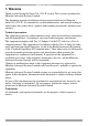
SMART 216 / 232 IP 1. Welcome Thank you for buying the Smart 216 / 232 IP system. This system is produced by Minicom Advanced Systems Limited. This document provides installation and operation instructions for Minicom’s Smart 216 / 232 IP. It is intended for system administrators and network managers, and assumes that readers have a general understanding of networks, hardware and software.
USER GUIDE Section I This section explains how to configure and operate the Smart 216 / 232 IP system remotely over IP. Section II on page 39, explains how to operate the Smart 216 / 232 IP switching system locally through the On Screen Display (OSD). 2. Introduction All references throughout this guide to the Smart 216 IP refer equally to the Smart 232 IP. The two units are functionally the same. The Smart 216 IP has 16 Server ports and the Smart 232 IP has 32 Server ports.
SMART 216 / 232 IP Security - Supports the highest security standards for encryption (128 bit SSL and HTTPS) and authentication for remote user and advanced OSD management with multi-layer security for local user. KVM.net - Can be controlled by the Minicom’s KVM.net system for centralized over-IP management of distributed data center locations. Seamless power control – with Minicom’s Serial Remote Power Switch. 4.
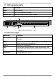
USER GUIDE 7.1 LED and button table LED Function Power Power Indicator Link Unit is connected to the network Remote 1 & 2 Illuminates when a remote session is active Monitor Serial 1 port Serial 2 port SERIAL 1 I 0 POWER 100-240 VAC 50/60 Hz SERIAL 2 LOCAL USER 1 LAN LAN (Ethernet) port Power 2 3 4 5 6 7 Mouse 8 9 SERVER 10 11 12 13 14 15 16 Server ports Keyboard Figure 2 Smart 216 IP ports – side 2 7.
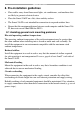
SMART 216 / 232 IP 8. Pre-installation guidelines • Place cables away from fluorescent lights, air conditioners, and machines that are likely to generate electrical noise • Place the Smart 216 IP on a flat, clean and dry surface • The Smart 216 IP is not intended for connection to exposed outdoor lines • Ensure that the maximum distance between each computer and the Smart 216 IP, does not exceed 30m/100ft for ROCs. 8.
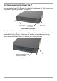
USER GUIDE 8.2 Rack mounting the Smart 216 IP Rack mount the Smart 216 IP using the supplied Rack-mount kit. The brackets can be placed in 2 possible positions, see Figure 3. Front of unit Position here for front facing Position here for rear facing Rear of unit Figure 3 Bracket positions Place the brackets towards the front of the unit so that the unit can be mounted front facing, or place the brackets towards the rear of the unit so that the unit can be mounted rear facing.
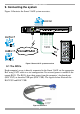
SMART 216 / 232 IP 9. Connecting the system Figure 5 illustrates the Smart 216 IP system overview. Figure 5 Smart 216 IP system overview 9.1 The ROCs Each computer/ server is directly connected to the Smart 216 IP via the appropriate RoC using CAT5 cable in a star configuration. No external power is needed at the remote ROCs. The ROCs draw their power from the computer’s keyboard port (ROC PS/2) or from the USB port (ROC USB). The figures below illustrate the ROC PS/2 and ROC USB.
USER GUIDE To computer’s Video Card To computer’s USB Port Figure 7 ROC USB 9.1.1 Connecting a ROC PS/2 Figure 8 illustrates the ROC PS/2 connections. You can connect the ROC PS/2 to a powered on computer, but it must be in the following order: 1. Connect the Mouse connector to the computer’s Mouse port. 2. Connect the Keyboard connector to the computer’s Keyboard port. 3. Connect the Screen connector to the computer’s Video port.
SMART 216 / 232 IP 9.1.2 Connecting a ROC USB The ROC USB supports Windows 98 SE and later, MAC, SUN and SGI, and all modern Linux distributions. The connections for ROC USB are exactly the same. Figure 9 illustrates the ROC USB and its connections. To connect the ROC USB: 1. Connect the Screen connector to the computer’s Video port. 2. Connect the USB connector to the computer’s USB port. To Video port To USB port ROC USB CAT5 cable to switch Server port Figure 9 ROC USB 9.
USER GUIDE 9.5 Connecting the power supply 1. Using the Power cord provided, connect the Smart 216 IP to a socket outlet with grounding connection. Only use the power cord supplied with the unit. 2. Switch on the Smart 216 IP. 10. Setting the IP address By default, Smart 216 IP boots with an automatically assigned IP address from a DHCP (Dynamic Host Configuration Protocol) server on the network. The DHCP server provides a valid IP address, gateway address and subnet mask.
SMART 216 / 232 IP In the Settings window navigate downwards using the Tab key. At the bottom of the window, press tab to go to the top of the window. Change settings by typing in the selected area or by pressing the spacebar – whichever is relevant. Changing the Network parameters Enable DHCP – When a DHCP server is active on the same network to which Smart 216 IP is connected, DHCP provides automatic IP assignment.
USER GUIDE 11.1 SSL Certificate notes When first connecting, 2 browser security warnings appear. Click Yes to proceed. The first warning disappears upon first Smart 216 IP client installation, when Minicom’s root certificate is installed. On first connection install the Minicom certificate and ActiveX control. You must login as an Administrator to your computer to install the ActiveX control. Once the ActiveX control is installed, all types of users can login. 11.
SMART 216 / 232 IP Figure 14 Targets page By default an Administrator can access all connected Targets, so they all appear on the Targets page. Columns: Server name - The server name can be changed in the configuration settings to give the server an identifiable name. Server Status - Server Status can be on, off or busy (i.e. another user is accessing the server). User – The current user (if any) accessing the Target. 11.
USER GUIDE Figure 15 Network >Configuration page 12.1 Network > Configuration Consult your Network Administrator for the network settings. Device name - Type a name for the Smart 216 IP. TCP Ports - Choose any 3 TCP ports from port #800 to 65535. (When managed by KVM.net® II, the port numbers can be changed from KVM.net GUI if needed). Notes Firewall or router security access list must enable inbound communication through the selected TCP ports for the Smart 216 IP’s IP address.
SMART 216 / 232 IP 12.1.2 KVM.net KVM.net is a centralized IP based system for secure control of servers and network devices, power and user administration in the data center environment. KVM.net combines Out-Of-Band, KVM via IP access with modern IT standards and requirements. It is the most comprehensive remote server maintenance solution available in the market today. Enable KVM.net - Check this option to allow Smart 216 IP unit to be remotely managed by Minicom’s KVM.net system.
USER GUIDE Administrator An Administrator has unrestricted access to all windows and settings. An Administrator can change the name and password and Target server permissions of all users. User A User can access/control permitted Target servers, but cannot use the advanced mouse settings. A User has no access to the web configuration interface. View only View only can view the screen of the currently accessed Target server without keyboard and mouse control.
SMART 216 / 232 IP 13.3 Blocking a user An alternative to deleting a user is blocking a user. This means that the user’s name and password is stored, but the user is unable to access the system. Check Block to block a user. Uncheck Block to allow the user access. 14. Administration > Switch Configuration Give the servers connected to the Smart 216 IP unique names, so that users accessing the system can identify the servers easily. To do so: 1. From the menu click Switch Configuration.
USER GUIDE 15. Administration > Power Management Where you have a Minicom Serial Remote Power Switch (SRPS), connect it to the Serial 1 port of the Smart 216 IP. Configure the Power Management switch as follows: 1. From the menu, click Power Management. The Power Management window appears, see Figure 17. Figure 18 Power Management 2. Select the number of sockets on the power management switch in the Number of Sockets drop-down menu (SRPS has 8) . The appropriate number of Managed by Sockets and 3.
SMART 216 / 232 IP 16. Administration > Serial Settings Where you have a Serial device connected to the system you must configure the RS232 settings. To do so: From the menu click Serial Settings, the Serial Settings appear, see Figure 19. Figure 19 Serial Settings Where you have a Minicom Serial Remote Power Switch, it must be connected to Serial port 1. For each Serial device connected, type a device name and choose the correct device parameters. 17.
USER GUIDE Figure 20 User Targets Configuration 2. Select a user from the User drop-down menu. 3. Check the Target servers the user can access (according to his access permissions). To select all Target servers, press . 4. Click Apply, the selection is saved. 5. Repeat the above steps for other users. 18. Security > Settings Configure the security features, such as Account Blocking, Password Policy and Idle Timeout, as explained below.
SMART 216 / 232 IP Password Policy For local and remote users you have the option of a standard or high security level of password. The table below shows the parameters of the 2 options.
USER GUIDE 20. Maintenance > Switch Upgrade Upgrade the Smart 216 IP firmware to take advantage of new features. Download the firmware from the Support section of Minicom’s website –www.minicom.com. Save the firmware file on the Client computer. From the menu select Switch Upgrade. The Upgrade window appears showing the current firmware version see Figure 23. Figure 23 Firmware Upgrade 1. Locate and upload the firmware file. 2. Verify the current and uploaded version of the firmware. 3. Click .
SMART 216 / 232 IP 5. Press , the firmware upgrades. Figure 24 RICCs/RoCs Upgrade 22. Restore Factory Settings You can restore the Smart 216 IP unit to the factory settings. This restores the original Smart 216 IP parameters, resetting all the information added by the administrators, including: Network settings*, servers, users, and passwords etc. * You have the option to preserve network settings – explained below. Warning! Once reset the data cannot be retrieved. To restore factory settings: 1.
USER GUIDE 23. Set Time & Date The time and date set is used when recording log events (see page 37). To set the time and date: From the menu, select Time & Date, Figure 26 appears. Figure 26 Set Time & Date Type the appropriate parameters. 24. Backup & Restore You can backup all configuration data and restore it at a later date. To do so: From the menu select Backup & Restore, Figure 27 appears. Figure 27 Backup & Restore To backup the configuration data, click . And save the file.
SMART 216 / 232 IP 26. Accessing a Target server Log in to the web interface as explained on page 13. The web interface opens at the Targets page, see Figure 14 on page 15. To connect to a Target or serial device, click the desired Target/device in the Server Name Column. (A server being used by another user cannot be accessed). The screen of the Target/device appears inside a remote console window. Note! For a User, only permitted Targets appear on the Targets page.
USER GUIDE When maximized, the Toolbar can be dragged and dropped to anywhere on the screen, by dragging the icon screen. . When minimized the icon glides to a side of the To hide the Toolbar, either: Double-click the Smart 216 IP System tray icon . Or Press F9. To display the Toolbar repeat the above action. See also page 36. 26.2 Switching to a different server To connect to a different server: , or right-click . A list of available servers 1. From the Toolbar, click appears.
SMART 216 / 232 IP Bandwidth Choose from the following options Adaptive – automatically adapts to the best compression and colors according to the network conditions. (Not recommended because network parameters may change frequently impacting on user experience). Low - Select Low for high compression and 16 colors. Medium - Select medium for medium compression and 256 colors. Medium is recommended when using a standard internet connection. High - For optimal performance when working on a LAN, select High.
USER GUIDE Figure 30 Manual Video Adjustments controls Brightness / Contrast - use the scales to adjust the brightness and contrast of the displayed image. Move the sliders to change the displayed image. Click in the area of the sliders for fine-tuning. For the following controls choose the appropriate measurement. Horizontal Offset - defines the starting position of each line on the displayed image. Vertical Offset - defines the vertical starting position of the displayed image.
SMART 216 / 232 IP 26.5 Power cycle Where a Minicom Serial Remote Power Switch is connected to Serial 1 port of the IP Control, you can power manage the Target servers as follows: . The Power menu appears, see below. From the Toolbar, click Figure 31 Power menu To send a power cycle command or to power down or up the currently accessed Target server, select the appropriate option.
USER GUIDE 2. Select the desired sequence and click OK. The sequence appears in the Special Key Manager box. 3. Click OK. The sequence appears in the Keyboard Key sequence list. To record a key sequence: 1. From the Special Key Manager box press Record New. The Add Special Key Dialog box appears, see Figure 33. Figure 33 Add Special Key Dialog box 2. Give the key sequence a name in the Label field. 3. Click Start Recording. 4. Press the desired keys. The key sequence appears in the area provided. 5.
SMART 216 / 232 IP Warning Before synchronizing mouse pointers adjust the video of the Target server, (explained above) otherwise mouse synchronization may not work. 26.7.1 Aligning the mice pointers When accessing the Target server, the mice may appear at a distance to each other. To align the mouse pointers: From the Toolbar click align. / Align or press Ctrl+M simultaneously. The mice 26.7.2 Calibrating mice pointers A Target server may have a different mouse pointer speed to the Client computer.
USER GUIDE Figure 34 Mouse Settings Dialog box 2. Select the Target server’s Operating System and click OK. Instructions and sliders appear. 3. Follow the instructions and set any relevant sliders to the same values as set in the Target server’s Mouse Properties window. 2 examples! For Windows XP, 2003 Server, Vista and 2008 Server. Go to the Mouse settings on the Target server and uncheck Enhance pointer precision. For Windows NT4, 98, ME, 2000.
SMART 216 / 232 IP 26.7.3.2 Advanced – Mouse Emulation the Mouse Emulation Dialog box appears, see Figure 35. Do not Click change these settings unless instructed to do so by Tech support. Figure 35 Mouse Emulation Dialog box Max Rate - this defines the maximum mouse report rate. For Sun Solaris the default value is 20 in order to support older Sun versions. 26.
USER GUIDE Figure 36 Client Configuration Dialog box Pointer type – From the Drop-down menu you can change the Client computer mouse pointer to appear as a dot or to not appear at all. Hide Toolbar – Check this option to hide the Toolbar from the next reconnection onwards. To toggle the Toolbar on and off, press F9 or double-click the System tray icon . See above page 27. Full Screen Mode - Check this option to make the remote session screen appear in full screen mode from the next reconnection onwards.
SMART 216 / 232 IP 27. The Targets page menu When logging into the system as an Administrator or a User, you reach the Targets page, see Figure 14 page 15. From the menu you can: • Change the password • See an event log Note! Only an Administrator has the configuration option in the menu. 27.1 Changing the password To change the password, from the menu click Password, the following appears. Figure 37 My Properties Type a new password according to the password policy set - see page 22. 27.
USER GUIDE Navigate through the events pages using the forward or backward arrows, marked as (A) in Figure 38, From the drop down menu, marked as (B) in Figure 38, choose the number of events that will appear on each page - between 10 – 40. 27.2.1 Downloading the log You can download and save the log. and save as a .csv file. The file can be To do so, click viewed using Microsoft Excel or compatible software. 27.2.2 Clearing the log To clear the log, click save the log. .
SMART 216 / 232 IP Section II Section II explains how to operate the Smart 216 IP system locally via the OSD. 28. The OSD To display the OSD: 1. From the local keyboard, press the left Shift key twice. The OSD Main window appears. See Figure 39. Lines with yellow text show active computers. Lines with blue text show inactive computers. The PM column indicates a server can be power managed. Port number appears here PM=Power management Instruction keys Figure 39 OSD Main window 28.
USER GUIDE 28.3 Power management hotkey – left Shift, F12 To power manage a server connected to a power management switch: 1. Navigate to the computer line you desire to power manage. 2. Press Left Shift, F12. The Power Control dialog box appears, see Figure 40. Note! If you change the OSD hotkey from Shift, Shift to Ctrl, Ctrl, then the power management hotkey becomes left Ctrl, F12. Figure 40 Power Control dialog box 3.
SMART 216 / 232 IP 28.5 Tuning – F5 You can tune the image of any computer screen from the Main window. To adjust the screen image: 1. Navigate to the computer line you wish to adjust. 2. Press F5. The screen image of the selected computer appears, together with the Image Tuning label, see Figure 42. Figure 42 Image Tuning label 3. Adjust the image by using the Right and Left Arrow keys. 4. When the image is satisfactory, press Esc. Note! Picture quality is relative to distance.
USER GUIDE From In the Settings window you can do the following: KVM.NET MNG – Press the spacebar to toggle between enabling and disabling KVM.net management. When enabled the Smart 216 IP unit is remotely managed by Minicom’s KVM.net system. KVM.NET ADD – Here you can change the static IP address of the KVM.net Manager. HOT KEY – By pressing Shift, Shift the OSD appears.
SMART 216 / 232 IP 28.8 Saving changes to the settings To save changes to the settings and return to the Main window, press Esc. 29.
USER GUIDE 30. Technical specifications Target server Windows, Novell, Linux, SUN Solaris Operating systems Client Computer Windows 2000 or higher with IE 6.0 or higher and ActiveX Target server Up to 1600 x 1200 @ 85Hz Resolution Client Computer Recommended - resolution should be higher than on Target server Distance from Switch to ROCs Up to 30m/99ft.
SMART 216 / 232 IP 31. Safety This device contains no serviceable parts. Any servicing of the device must be performed by an authorized Minicom Technician in a Minicom authorized Service Center. 32. User guide feedback Your feedback is very important to help us improve our documentation. Please email any comments to: ug.comments@minicom.com Please include the following information: Guide name, part number and version number (as appears on the front cover). 33.
USER GUIDE Regional Offices Germany France Italy Kiel Vincennes Rome Tel: + 49 431 668 7933 info.germany@minicom.com Tel: + 33 1 49 57 00 00 info.france@minicom.com Tel: + 39 06 8209 7902 info.italy@minicom.com England China Asia Pacific / S. Korea Tel: + 44 121 288 0608 info.uk@minicom.com Tel: +86 21 6445 3181 Info.china@minicom.com Tel: +972 2 535 9618 info.ap@minicom.com www.minicom.