
User guide

Installation
Pre-Installation Guidelines
User Guide | 17
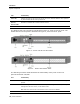
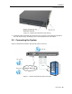
Port Functionality
Flash
For updating firmware of the analogue part of the Smart 216/232 IP system - OSD,
Switch, RICCs, and ROCs.
LAN
For connecting to the 10/100 Mbit Ethernet. The LED illuminates yellow when the unit is
connected to LAN; green when a remote session is in progress.
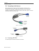
Server ports
For connecting to the servers via ROCs
.
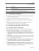
2.3 Pre-Installation Guidelines
Place cables away from fluorescent lights, air conditioners, and machines that are
likely to generate electrical noise.
Place the Smart 216/232 IP unit on a flat, clean and dry surface.
The Smart 216/232 IP unit is not intended for connection to exposed outdoor
lines.
Ensure that the maximum distance between each computer and the Smart
216/232 IP unit, does not exceed 30 m / 100 ft for ROCs.
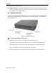
2.4 Rack Mounting the Smart 216/232 IP Unit
2.4.1 Rack Mounting Safety Considerations
When mounting Smart 216/232 IP onto a rack, avoid the following conditions:
Elevated operating ambient temperature – The operating ambient temperature of
the rack environment may be greater than the room ambient temperature.
Therefore, take special care when installing the unit in a closed or multi-unit rack
assembly that the environment is compatible with the maximum rated ambient
temperature.
Reduced airflow – Install the equipment in a rack in such a way that the amount of
airflow required for safe operation is not compromised. Leave a gap of at least 5
cm / 2” on each side of Smart 216/232 IP.
Uneven mechanical loading – Uneven loading can cause damage to the equipment
or personal injury. Mount the equipment in the rack in such a way that a
hazardous condition does not result due to uneven mechanical loading.
Circuit overloading – When connecting the equipment to the supply circuit, make
sure that the total power of all the components does not exceed the circuit
capabilities. Overloading of circuits can affect over-current protection and supply
wiring, potentially resulting in fire and shock hazards.