
User guide

Installation
System Components
16 | Smart 216/232 IP
LED Functionality
Power LED
Indicates the state of the Smart 216/232 IP unit: Green indicates that the unit is powered
on; Red indicates that the unit is powered off.
Remote 1,
Remote 2 LEDs
Illuminate to indicate that a remote session is active.
Link
Illuminates to indicate that the unit is connected to the network.
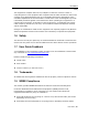
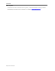
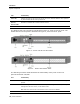
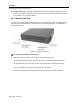
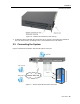
The Smart 216 IP unit rear panel is illustrated in Figure 2; it has 16 server ports. The
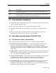
Smart 232 IP unit rear panel is illustrated in Figure 3; it has 32 server ports.
Figure 2 – Smart 216 IP Unit Rear Panel
Figure 3 – Smart 232 IP Rear Panel
The following connector table describes the functionality of the ports on the rear
panel of the Smart 216/232.
Port Functionality
Console KVM
For connecting a keyboard, video, and mouse to operate the Smart 216/232 IP locally;
optional.
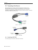
Serial 1
For connecting the Smart 216/232 IP unit to any serial manageable devices, such as power
management units and routers, via the RS232 cable.
Note: Minicom’s Serial Remote PowerSwitch must be connected to Serial 1.
Serial 2
For connecting the Smart 216/232 IP unit to any Serial device.