
User guide


USER GUIDE
4
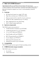
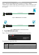
Figure 1 illustrates the KVMS Extender system as an extender, with the
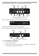
Transmitter up to 300m/1,000ft away from the Receiver. Figure 2 illustrates a dual
control scenario, whereby either the local or extended user can access and control
the computer.
MINICOM
KVMS Extender
Transmitter
Link
Power
ActiveLocked
MINICOM
KVMS Extender
Receiver
LinkPowerActiveLocked
Computer
Transmitter
Receiver
CAT5 cable 300m/1,000ft
KVM
Serial
KVM
Serial
Figure 1 KVMS Extender as an extender
MINICOM
KVMS Extender
Transmitter
Link
Power
ActiveLocked
MINICOM
KVMS Extender
Receiver
LinkPowerActiveLocked
Computer
Transmitter
Receiver
CAT5 cable 300m/1,000ft
KVM
Serial
KVM
Serial
KVM
Serial
Figure 2 KVMS Extender in a dual control scenario
7. The KVMS Extender units
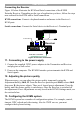
Figure 3 illustrates the front panel of the KVMS Extender Transmitter.
MINICOM
KVMS Extender
Transmitter
Link
Power
ActiveLocked
Figure 3 KVMS Extender Transmitter front
The table below explains the LEDs.
LED Meaning
Power Power indicator
Link System cable connected to Transmitter and Receiver
Active Steady: This unit currently has control. Blinking: The other currently has control.
Locked The other unit has locked control preventing this unit from taking control