KVMS Extender User Guide w w w . m i n i c o m . c o m International HQ North American HQ European HQ Jerusalem, Israel Linden, NJ, USA Dübendorf, Switzerland Tel: + 972 2 535 9666 minicom@minicom.com Tel: + 1 908 486 2100 info.usa@minicom.com Tel: + 41 44 823 8000 info.europe@minicom.com Technical support - support@minicom.com 5UM30165 V1.
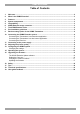
KVMS EXTENDER Table of Contents 1. 2. 3. 4. 5. 6. 7. 8. 9. 10. 11. 12. 13. 14. 15. 16. 17. 18. 19. Welcome............................................................................................................................................... 2 What is the KVMS Extender? ............................................................................................................ 3 Features .............................................................................................................
USER GUIDE 1. Welcome Thank you for buying the KVMS Extender system. This system is produced by Minicom Advanced Systems Limited. This document provides installation and operation instructions for Minicom’s KVMS Extender. Technical precautions This equipment generates radio frequency energy and if not installed in accordance with the manufacturer’s instructions, may cause radio frequency interference. This equipment complies with Part 15, Subpart J of the FCC rules for a Class A computing device.
KVMS EXTENDER 2. What is the KVMS Extender? The KVMS Extender gives KVM & Serial extension and control up to 300m/1000ft away. It provides superior video quality over long distances and is an excellent solution for clean rooms, kiosks, museums, banks and any other places that need to keep their computers in a secure or environmentally controlled location. 3.
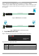
USER GUIDE Figure 1 illustrates the KVMS Extender system as an extender, with the Transmitter up to 300m/1,000ft away from the Receiver. Figure 2 illustrates a dual control scenario, whereby either the local or extended user can access and control the computer.
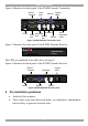
KVMS EXTENDER Figure 4 illustrates the back panel of the KVMS Extender Transmitter. RS232 Terminal Video card www.minicom.com TERMINAL Monitor COMPUTER System cable CONSOLE 5VDC COMPUTER SYSTEM Keyboard Keyboard Serial port Mouse Mouse port port Power SERVICE Serial Download cable Figure 4 KVMS Extender Transmitter back Figure 5 illustrates the front panel of the KVMS Extender Receiver.
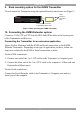
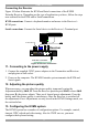
USER GUIDE 9. Rack mounting option for the KVMS Transmitter To rack mount the Transmitter using the optional brackets and screws see Figure 7. Insert screws to connect to rack MINICOM KVMS Extender Power Link Active Locked Transmitter Insert screws to connect to Transmitter side panel Figure 7 Rack mounting the KVMS Transmitter 10. Connecting the KVMS Extender system Connect a CATx UTP or FTP 2x4x24 AWG Solid Wire cable to the System ports of the Transmitter and Receiver.
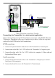
KVMS EXTENDER KB Mouse 100T Parallel Serial A Transmitter Serial B www.minicom.com Video TERMINAL COMPUTER CONSOLE 5VDC COMPUTER SYSTEM Serial Extender cable SERVICE CAT5 cable to Receiver 3 in 1 CPU cable Figure 8 Transmitter connections – Extender Connecting the Transmitter for a dual control application Figure 9 below illustrates the KVM and Serial connections of the KVMS Extender Transmitter.
USER GUIDE P110 KB SD Mouse To Serial device 100T Parallel Serial A Transmitter Serial B www.minicom.com Video TERMINAL COMPUTER CONSOLE 5VDC COMPUTER SYSTEM Serial Extender cable SERVICE CAT5 cable to Receiver 3 in 1 CPU cable Figure 9 Transmitter connections – dual control Note! Although we recommend connecting the Transmitter to a switched off computer, you can connect it to a switched on computer. To do so you must connect it in the following order: 1.
KVMS EXTENDER Connecting the Receiver Figure 10 below illustrates the KVM and Serial connections of the KVMS Extender Receiver. Depending on the type of application you have, follow the steps now outlined for the KVM and/or Serial connections. KVM connections: Connect a keyboard monitor and mouse to the Receiver’s KVM ports.
USER GUIDE All adjustments are made from the Receiver position. To enter the KVMS Settings: 1. Ensure that the input language is English. Check the language icon in the Systray . 2. Open any text editor, e.g. Notepad or Word. 3. Press Shift, release Shift then press F2. The settings instructions appear see Figure 11. Figure 11 Settings instructions 4. Press F6 to see the current configuration, see Figure 12.
KVMS EXTENDER To change a setting: 1. Press the keyboard number to enter the setting. 2. Press the keyboard letter of the desired option. 3. Press Enter until a confirmation appears that the settings are saved. Once saved you exit the option. Or Press q to exit the option without saving. 4. Press Esc to exit the KVMS settings. Note 1: Video quality adjustments can also be done using a hotkey with 6 preset adjustments as explained in the Video brightness and tuning section below.
USER GUIDE 3 Take control When control is not locked at one position, the non-controlling position can gain control after a period of inactivity (timeout) or by pressing the hotkey Shift, F10. Choose the method for taking control from the other position, either by timeout (default) or hotkey. Tip! For an extender application set switching control to be by timeout.
KVMS EXTENDER Update the DDC information if you replace the monitor. For a dual control scenario, we recommend using similar monitors at both locations. When the monitors are not similar, input the DDC information of the lower resolution monitor.
USER GUIDE Press a letter key according to the list below and press the right or left arrow key to adjust the image. · · · · · Notes: [l]uminance – image brightness [e]qualization – image sharpness [r]ed delay – explained below [g]reen delay– explained below [b]lue delay– explained below (a) When you press one of the above letters, all three keyboard LEDs blink indicating that you are in adjustment mode.
KVMS EXTENDER 14. Operating the system In general the system is controlled in a first come first served basis, with either the Transmitter or Receiver position taking control. The other position can gain control by using the mouse/keyboard after the period of inactivity (timeout), or by pressing the hotkey Shift, F10 – depending on the method chosen in the KVMS Extender settings– see pages 12 and 12. Lock disable/enable By default Lock is disabled.
USER GUIDE To Serial port Serial Download cable www.minicom.com TERMINAL COMPUTER Update software installed here CONSOLE 5VDC COMPUTER SYSTEM SERVICE Transmitter CAT5 cable to Receiver Figure 15 Serial Download cable The KVMS Extender Update software Start the KVMS Extender Update software. The Update Utility window appears, see Figure 16. Select Transmitter or Receiver here Figure 16 Update Utility window The table below explains the functions of the buttons and boxes.
KVMS EXTENDER Verifying the version numbers Before upgrading the firmware, you must verify which firmware and hardware versions the units have. To verify the Transmitter version numbers: 1. Select Transmitter. 2. Click . The firmware version number appears. 3. Click . The hardware version number appears. To verify the Receiver version numbers: Select Receiver then follow steps 2 and 3 above.
USER GUIDE 16. Safety The device must only be opened by an authorized Minicom technician. Disconnect device from AC mains before service operation! 17. Tips Below is a summary of the tips found throughout this guide.
KVMS EXTENDER 18.
USER GUIDE 19. User guide feedback Your feedback is very important to help us improve our documentation. Please email any comments to: ug.comments@minicom.com Please include the following information: Guide name, part number and version number (as appears on the front cover). © Copyright 2007 Minicom Advanced Systems Ltd.
KVMS EXTENDER Regional Offices Germany France Italy Kiel Vincennes Rome Tel: + 49 431 668 7933 info.germany@minicom.com Tel: + 33 1 49 57 00 00 info.france@minicom.com Tel: + 39 06 8209 7902 info.italy@minicom.com England Camberley Tel: + 44 (0) 1276 25053 info.uk@minicom.com www.minicom.
USER GUIDE 22