IP Control User Guide w w w . m i n i c o m . c o m International HQ North American HQ European HQ Jerusalem, Israel Linden, NJ, USA Dübendorf, Switzerland Tel: + 972 2 535 9666 minicom@minicom.com Tel: + 1 908 486 2100 info.usa@minicom.com Tel: + 41 44 823 8000 info.europe@minicom.com Technical support - support@minicom.com 5UM70166 V1.
IP CONTROL Table of Contents 1. Welcome ...................................................................................................................... 3 2. Introduction ................................................................................................................. 4 3. Key features ................................................................................................................ 4 4. System components...................................................................
USER GUIDE 23.8 Keyboard key sequences ............................................................................................................... 22 23.9 Synchronizing mouse pointers ....................................................................................................... 24 23.9.1 Aligning the mice pointers ...................................................................................................... 24 23.9.2 Calibrating mice pointers ............................................
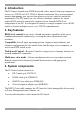
IP CONTROL 1. Welcome Thank you for buying the IP Control system. This system is produced by Minicom Advanced Systems Limited. This document provides installation and operation instructions for Minicom’s IP Control. It is intended for system administrators and network managers, and assumes that readers have a general understanding of networks, hardware and software.
USER GUIDE 2. Introduction The IP Control extends your KVM (keyboard, video, mouse) from any computer or server over TCP/IP via LAN, WAN or Internet connection. Now you can control, monitor and manage your servers from wherever you are, inside or outside the organization. The IP Control is a cost-effective hardware solution, for secure remote KVM access & control of a computer/server from the BIOS level independent of the OS.
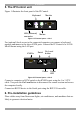
IP CONTROL 5. The IP Control unit Figure 1 illustrates the front panel of the IP Control. Monitor Keyboard LAN LAN (Ethernet) connector Mouse Figure 1 IP Control ports – side 1 For (optional) local access to the connected computer you connect a keyboard, monitor and mouse to the above KVM ports. Connect the IP Control to a 10/100 Mbit Ethernet using the LAN port. KVM In Serial Go Local button Power KVM In Serial Go Local 3.
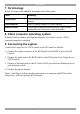
USER GUIDE 7. Terminology Below are some terms and their meanings used in this guide. Term Meaning Target server The computers/servers that are accessed remotely via the IP Control. Client computer The PC running a remote IP Control session Remote Session The process of accessing and controlling Target Servers connected to IP Control from a User workstation 8. Client computer operating system Windows 2000 or higher, with Internet Explorer 6.0 or later version.
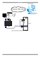
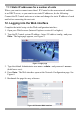
IP CONTROL User over IP Internet / VPN / LAN P110 SD LAN MINICOM Target PC IP CONTROL KVM In Serial KVM cable 3.
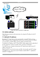
USER GUIDE User over IP Internet / VPN / LAN P110 KVM switch SD STATION 2 SER IAL MOUSE POWER KB PS/2 MOUSE SCREEN C OMPU TE R 5 C OMPU TE R 6 COMPUTER 7 COMPU TER 8 C OMPU TE R 1 COMPUTER 2 COMPU TER 3 C OMPU TE R 4 KVM cable Pr oLi ant DL3 60 9.1 - GB 10 k ULT RA2 SCSI 9.1 - GB 1 0k ULTRA2 SCSI Pr oLi ant DL3 60 LAN 9.1 - GB 10 k ULT RA2 SCSI MINICOM 9.1 - GB 1 0k ULTRA2 SCSI Pr oLi ant DL3 60 9.1 - GB 10 k ULT RA2 SCSI 9.1 - GB 1 0k ULTRA2 SCSI Pr oLi ant DL3 60 9.
IP CONTROL 11.1 Static IP addresses for a number of units Where you want to connect more than 1 IP Control to the same network and there is no DHCP server, or you want to use static IP addresses, do the following: Connect the IP Control units one at a time and change the static IP address of each unit before connecting the next unit. 12. Logging into the Web interface Complete the initial setup via the Web configuration interface: 1. Open your Web browser (Internet Explorer version 6.0 or higher). 2.
USER GUIDE 12.1 SSL Certificate notes When first connecting to IP Control’s https configuration page, 2 browser security warnings appear. Click Yes to proceed. The first warning disappears upon first IP Control client installation, when Minicom’s root certificate is installed. 13. Network > Configuration Consult your Network Administrator for the network settings. Device name - Type a name for the IP Control. Default device name consists of the letter ‘D’ followed by the 6-digit device number (D.N.
IP CONTROL 15. Administration > User Settings From the menu click User Settings, Figure 7 appears. Figure 7 User Settings On this page an Administrator creates and edits users. There are 3 levels of user access: · Administrator · User · View only Administrator An Administrator has unrestricted access to all windows and settings and can “take over” any active session (explained in section 23.1 on page 18). An Administrator can change the name and password of all users.
USER GUIDE 15.1 Adding a user To add a user: and type a name and a password. The password must be at 1. Click least 6 characters – letters or numbers, and must not include the user name, even if other characters are added. Note! The following “special” characters: &, <, >, ”, {, } cannot be used for either the user name or password. Depending on the security level chosen the user name and password parameters are different. See section 18 on page 14. 2. Select the permission type from the Permission box. 3.
IP CONTROL To do so: 1. From the menu click Switch Configuration. The KVM Switch Configuration window appears, see Figure 8. Figure 8 Switch Configuration 2. Choose the manufacturer and model of the connected KVM switch. The number of possible connected servers appears in the Server Name section. 3. Change the name of the connected servers by highlighting the server and typing a new name. Click to save changes. Note! Server names left as UNUSED cannot be accessed. Sync.
USER GUIDE 17. Administration > Serial Settings Where you have a Serial device connected to the system you must configure the RS232 settings. To do so: From the menu click Serial Settings, the Serial Settings appear, see Figure 9. Figure 9 Serial Settings Type a device name and choose the correct device parameters. Note! Where you have a Minicom Serial Remote Power Switch connected, see below Assign to RPS. 17.
IP CONTROL Figure 10 Security Settings The security Settings elements: Account Blocking – decide on the number of attempts to login with a wrong username or password after which there is a time lock or a total block. Password Policy – You have the option of a standard or high security level of password. The table below shows the parameters of the 2 options.
USER GUIDE Figure 11 Install SSL Certificate page Certificate File - Browse to locate the cer file. Private File - Browse to locate the private key file. Key Password - Type the “private key” password. Click . 20. Maintenance > Firmware Upgrade Upgrade the IP Control firmware to take advantage of new features. Download the firmware from Minicom’s website. Save the firmware file on the Client computer. From the menu select Firmware Upgrade. The Firmware Upgrade appears see Figure 12.
IP CONTROL 21. Restore Factory Settings You can restore the IP Control unit to the factory settings. This restores the original IP Control parameters, resetting all the information added by the administrators, including: Network settings*, Servers, Switches, Users, Passwords etc. * You have the option to preserve Network settings – explained below. Warning! Once reset the data cannot be retrieved. To restore factory settings: 1. From the menu select Restore Factory Settings.
USER GUIDE Figure 14 Remote session window 23.1 Taking over a busy remote session When connecting to a busy Target Server an Administrator has the option to take over the Target Server. A User only has this option when the current session is run by another User, but not by an Administrator. The following message appears Figure 15 Busy remote session options Choose to Take Over or View Only or Cancel. 23.
IP CONTROL 3. Right click the Internet Explorer menu bar and check Auto-Hide. The Internet Explorer menu bar disappears. You are in full screen mode. To exit full screen mode: Press F11. Or place the mouse at the top of the window to display the Internet Explorer toolbar and click the Restore button. Note! Full screen mode can also be activated from the Toolbar menu, see page 27. 23.
USER GUIDE Figure 16 Settings.. box Bandwidth Choose from the following options Adaptive – automatically adapts to the best compression and colors according to the network conditions. Low - Select Low for high compression and 16 colors. Medium - Select medium for medium compression and 256 colors. Medium is recommended when using a standard internet connection. High - For optimal performance when working on a LAN, select High. This gives a low compression and high colors (16bit).
IP CONTROL 23.6.2 Manual Video Adjust Use the manual video adjustment for fine-tuning the Target Server video settings after auto adjustment or for adapting to a noisy environment or a non-standard VGA signal or when in full-screen DOS/CLI mode. To adjust the video manually: Click Manual Video Adjust. The manual controls appear, see Figure 17. Also a red frame appears around the screen. This represents the screen area according to the Server's screen resolution.
USER GUIDE 23.6.3 Auto Video Adjust To adjust the video automatically: Click Auto Video Adjust. The process takes a few seconds. If the process runs for more than 3 times, there is an abnormal noise level. Check the video cable and verify that no dynamic video application is running on the Target Server’s desktop. Perform the procedure where necessary for each Target Server or new screen resolution. 23.
IP CONTROL Figure 19 Special Key Manager box To add a predefined sequence: 1. Click Add Predefined. A list of sequences appears. 2. Select the desired sequence and click OK. The sequence appears in the Special Key Manager box. 3. Click OK. The sequence appears in the Keyboard Key sequence list. To record a key sequence: 1. From the Special Key Manager box press Record New. The Add Special Key box appears see Figure 19. Figure 20 Add Special Key box 2. Give the key sequence a name in the Label box. 3.
USER GUIDE To edit a key sequence: 1. From the Special Key Manager box select the desired key. 2. Click Edit. 3. Click Start Recording 4. Press the desired keys. The keys appear in the area provided. 5. Click Stop Recording. 6. Click OK. 23.9 Synchronizing mouse pointers When working at the Client computer, two mouse pointers appear: The Client computer’s is on top of the Target Server’s. The mouse pointers should be synchronized. The following explains what to do if they are not synchronized.
IP CONTROL Note! If the mouse settings on the Target Server were ever changed, you must synchronize mouse pointers manually, as explained below. 23.9.3 Manual mice synchronization If the mouse settings on the Target Server were ever changed, or when the Operating system on the Target Server is, Windows XP / 2003 Server / Vista, Linux, Novell, SCO UNIX or SUN Solaris you must synchronize the mouse pointers manually. To manually synchronize mouse pointers: 1. From the Toolbar click appears see Figure 21.
USER GUIDE 23.9.3.1 USB The USB option in Mouse Settings box is available for RICC and X-RICC USB and Phantom Specter USB and for unsupported operating systems and SUN Solaris. Use this option if you are sure of the custom acceleration algorithm you are using, or have been informed so by customer support. 23.9.3.2 Advanced – Mouse Emulation In the Advanced Mouse settings, you can set the type of mouse that you would like IP Control to emulate.
IP CONTROL About - Click About to verify the Client, Firmware, KME (Keyboard/Mouse Emulation firmware) and Switch file versions installed on your IP Control. Local Settings – Click Local settings, the Client Configuration box appears, see Figure 23 Figure 23 Client Configuration box Pointer type – From the Drop-down menu you can change the Client computer mouse pointer to appear as a dot or to not appear at all. Hide Toolbar – Check this option to hide the Toolbar from the next reconnection onwards.
USER GUIDE Figure 24 Login box 4. Type username: admin , password: SAFEmode. (Case sensitive). This username and password works only after the reset procedure described above. A menu appears. 5. From the menu choose Restore Factory Settings. A warning appears see Figure 25. Figure 25 Restore factory settings 6. Check the box if you want to preserve Network settings. 7. Click 8. Select Restore. The factory defaults are restored. When the process finishes Figure 26 appears. Figure 26 Reboot 9.
IP CONTROL 25. Technical specifications Target Server DOS, Windows Vista, Novell, Linux, SUN Solaris for PC Operating systems Client Computer Windows 2000 or higher with IE 6.
USER GUIDE 640x480 x x 720x400 800x600 x x x x x x x x x 1024x768 x x x x x 1152x864 x x x x x x 1152x900 x 1280x720 x 1280x768 x 1280x960 x 1280x1024 x 1600x1200 x x x x x X x x x x x x 27. Safety The device must only be opened by an authorized Minicom technician. Disconnect device from AC mains before service operation! 28. User guide feedback Your feedback is very important to help us improve our documentation. Please email any comments to: ug.comments@minicom.
IP CONTROL Regional Offices Germany France Italy Kiel Vincennes Rome Tel: + 49 431 668 7933 info.germany@minicom.com Tel: + 33 1 49 57 00 00 info.france@minicom.com Tel: + 39 06 8209 7902 info.italy@minicom.com England Camberley Tel: + 44 (0) 1276 25053 info.uk@minicom.com www.minicom.
USER GUIDE 32