
User guide


USER GUIDE
For further information about IMPI 1.5, see
i/tools.htm
http://developer.intel.com/design/servers/ipm
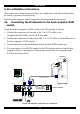
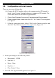
To use the IPMI over a serial interface enable it in the host computer. This is done
using BIOS settings or special utilities provided by the server manufacturer. Refer to
the server manufacturer's manual site.
Note! IPMI V1.5 is only supported by server systems manufactured in 2002
onwards.
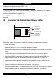
13. Connecting the Internal Reset/Power Option
Figure 8 shows the top view of the reset/power bracket.
To Reset pin
on Mainboard
To front panel
Reset switch
To Power On pin
on Mainboard
To front panel
Power switch
Figure 8 Reset/power bracket
Additional cables are required to enable the remote reset and power functions.
To install the bracket:
1. Mount the bracket in a free slot of the controlled system.
2. Find and disconnect the cable connecting the front panel reset button to the main
board.
3. Connect the cable to the pin connector on the bracket as shown in Figure 8.
4. Take the red/black reset cable and connect one end to the Motherboards reset
jumper connector and the other end to the bracket connector see Figure 8.
5. Find and disconnect the cable connecting the front panel power button and the
Motherboard.
6. Connect it to the pin connector on the bracket. See Figure 8.
7. Take the red/black power cable and connect one end to the Motherboard 's power
jumper connector and the other end to the bracket connector, see Figure 8.
12