
User guide
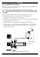


SMART IP EXTENDER
POWER
85-265VAC 50/60 Hz
USER COMPUTE R / SWITCH
ETHERNE T
ISDN
www.minicom.com
SERIAL 1 SERIAL 2
SD
P110
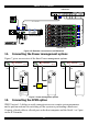
Smart IP Extender
3in1CPUcable
Computer rack
COMPUTER 1 COMPUTER 2
COMPUTER 6COMPUTER 5STATION 2
SCREENPS/2 MOUSEKB
POWER
SERIAL M OUSE
COMPUTER 3 COMPUTER 4
COMPUTER 8COMPUTER 7
ProLiant DL360
9.1 - GB
10k
ULTR A2 SC SI
9.1 - GB
10k
ULTRA2 SCSI
ProLiant DL360
9.1 - GB
10k
ULTR A2 SC SI
9.1 - GB
10k
ULTRA2 SCSI
ProLiant DL360
9.1 - GB
10k
ULTR A2 SC SI
9.1 - GB
10k
ULTRA2 SCSI
ProLiant DL360
9.1 - GB
10k
ULTR A2 SC SI
9.1 - GB
10k
ULTRA2 SCSI
ProLiant DL360
9.1 - GB
10k
ULTR A2 SC SI
9.1 - GB
10k
ULTRA2 SCSI
ProLiant DL360
9.1 - GB
10k
ULTR A2 SC SI
9.1 - GB
10k
ULTRA2 SCSI
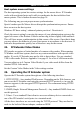
KVM switch
Figure 6 IP Extender connections to a KVM switch
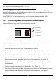
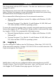
11. Connecting the Power management options
Figure 7 gives an overview of the three Power management options.
Reset/Power bracket
IPMI KVM
Connects to Reset and
Power On/Off pins on
Mainboard or Internal
Adapter kit
Server
ServerServer
KVM KVMIPMI
External power
Switch box
IPMI
IPMI version
1.5 interface
MINICOM
GI
ERV
F
RESET
IP Extender
SMART
MINICOM
GI
ERV
F
RESET
IP Extender
SMART
MINICOM
GI
ERV
F
RESET
IP Extender
SMART
Figure 7 Power management options
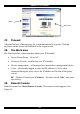
12. Connecting the IPMI option
IPMI Version 1.5 defines a serial connection to access certain system parameters
and to perform actions like switching off the system or performing a hard reset.
Connect a Serial cable to a Serial port on the host computer and the Serial 1 or 2 port
on the IP Extender.
11