
User guide

SMART IP EXTENDER
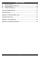
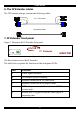
8. The IP Extender rear panel ports
The figure below illustrates the ports on the IP Extender.
POWER
85-265VAC 50/60 Hz
USER COMPUTER / SWITCH
ETHERNET
ISDN
www.minicom.com
Video InPower connector
Mouse
In port
Keyboard
Out
Mouse
Out
Keyboard
In port
Serial 1
SERIAL 1 SERIAL 2
Video Out Serial 2 ISDN
Ethernet
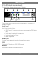
Figure 4 IP Extender ports
You can work locally on the host system by connecting a KVM console to IP
Extender rear panel.
Serial 1 port
Serial 1 port is used as follows:
• IPMI Version 1.5 connection to the remote system using the IPMI Option
cable
• Serial output for modem dial in connection
• Serial pass-through via Telnet
• Initial configuration
Serial 2 port
The Serial 2 port supports the internal and external power options
ISDN
Connects the IP Extender to a EURO ISDN network
Ethernet
Connects the IP Extender to an Ethernet network.
9