Smart IP Access User Guide Supported by: Rackit ® Technology Corporation 274 Madison Avenue, New York, NY 10016 Tel: (212) 679-0050 • Fax: (212) 679-0040 ® Technology Corporation 1 . 8 0 0 . 6 3 6 . 3 4 3 4 www.RackitTechnology.com International HQ North American HQ European HQ Italy Jerusalem, Israel Linden, New Jersey Dübendorf, Switzerland Rome Tel: + 972 2 535 9666 minicom@minicom.com Tel: + 1 908 4862100 Tel: + 41 1 823 8000 info.usa@minicom.com info.europe@minicom.com www.minicom.
SMART IP ACCESS Table of Contents Welcome ...........................................................................................3 1. 2. 3. 4. 5. 6. 7. Introduction..................................................................................4 Key Features ...............................................................................4 System components ....................................................................4 The Smart IP Access unit ...................................................
USER GUIDE 29. 30. 31. 32. 33. 34. Operating through a local KVM console.....................................25 Getting Started ..........................................................................25 Full screen mode.......................................................................26 The Toolbar elements................................................................27 Reset.........................................................................................
SMART IP ACCESS Welcome The Smart IP Access system is produced by Minicom Advanced Systems Limited. This document provides installation and operation instructions for Minicom’s Smart IP Access. It is intended for system administrators and network managers, and assumes that readers have a general understanding of networks, hardware and software.
USER GUIDE 1. Introduction The Smart IP Access extends your KVM (keyboard, video, mouse) from any computer or server over TCP/IP via LAN, WAN or Internet connection. Now you can control, monitor and manage your servers from wherever you are, inside or outside the organization. The Smart IP Access is a cost-effective hardware solution, for secure remote KVM access & control of a computer/server from the BIOS level - independent of the OS.
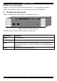
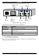
SMART IP ACCESS RS232 Cross cable option Smart IP Access has two RS232 RJ45 connectors. You can purchase another RS232 Cross cable to connect a second Serial device. P/N 5CB00566 4. The Smart IP Access unit Figure 1 illustrates the front panel of the Smart IP Access. MINICOM Power SMARTIPACCESS Remote Local Reset Figure 1 Smart IP Access front panel The table below lists the LEDs, buttons and functions.
USER GUIDE The figure below illustrates the rear panel of the Smart IP Access. SERIAL 1 and 2 RS232 connectors Computer Video card Monitor www.minicom.com 1 1 L A N POWER 100-240 VAC 50/60 Hz Power connector 2 2 S E R I A L LAN 1 and 2 Ethernet connectors CONSOLE COMPUTER Computer Mouse port Computer Keyboard port Mouse Keyboard Figure 2 Smart IP Access rear panel The table below lists the rear connectors and functions.
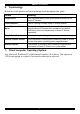
SMART IP ACCESS 6. Terminology Below are some phrases and their meanings used throughout this guide. Phrase Meaning Target Server The computers/servers that are accessed remotely via the Smart IP Access. Client computer The PC running a remote Smart IP Access session Smart IP Access Toolbar Menu Toolbar Menu displayed at the User station Internet explorer once the Smart IP Access client component is installed, facilitating control and adjustments of Smart IP Access operations.
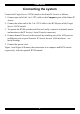
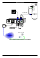
USER GUIDE Connecting the system Connect the Target Server / KVM switch to the Smart IP Access as follows: 1. Connect one end of the 3 in 1 CPU cable to the Computer ports of the Smart IP Access. 2. Connect the other end of the 3 in 1 CPU cable to the KVM ports of the Target Server / KVM switch. 3. To operate the KVM switches and Servers locally, connect a keyboard, mouse and monitor to the IP Access’s Local Console connectors. 4.
SMART IP ACCESS P110 SD 3 in 1 CPU cable www.minicom.
USER GUIDE P110 KVM switch SD STATION 2 SERIAL MOUSE POWER KB PS/2 MOUSE SCREEN COMPUTER 5 COMPUTER 6 COMPUTER 1 COMPUTER 2 3 in 1 CPU cable ProLiant D L3 60 9 .1 - GB 10k ULTR A2 SC SI 9.1 - GB 10k U LTR A 2 SCS I ProLiant D L3 60 9 .1 - GB 10k ULTR A2 SC SI 1 9 .1 - GB 10k ULTR A2 SC SI 1 S E R I A L L A N POWER 100-240 VAC 50/60 Hz 9.1 - GB 10k U LTR A 2 SCS I ProLiant D L3 60 www.minicom.com 2 CONSOLE 9.1 - GB 10k U LTR A 2 SCS I COMPUTER ProLiant D L3 60 9 .
SMART IP ACCESS Initial Settings The following sections provide instructions for setting the IP address for the Smart IP Access unit. 8. Default IP address Smart IP Access has two available Ethernet Adapters, LAN 1 and LAN 2: • By default, LAN 1 boots with an automatically assigned IP address if a DHCP (Dynamic Host Configuration Protocol) server exists. The MAC address appears on a label on the underside of the IP Access box. Also on the label is the 6-digit device number (D.N.).
USER GUIDE Figure 5 The Login page 3. Type the Administrator user name and password. By default, the user name is: admin and the password is access (both lower case). 4. Press Enter. The Web interface appears. See Figure 6. 5. Bookmark the page for easy reference. Figure 6 Smart IP Access Web interface SSL Certificate notes Upon first connection to Smart IP Access’s https configuration web page, 2 browser security warnings appear. Click Yes to proceed.
SMART IP ACCESS The second warning can be avoided by adding a line to your window’s ‘hosts’ file (typically at \winnt\system32\drivers\etc\hosts – edit with Notepad) The line format should be: any-IP any-name.kvm.net Example: 10.0.0.200 IPaccess.kvm.net From now on, you can browse to Smart IP Access by typing (or book-marking) https:// IPAccess.kvm.net. Minicom dedicates the kvm.net domain to this usage. You can use any device name except for www.kvm.net that is reserved by Minicom. 10.
USER GUIDE When checked, enables the Dynamic Host Configuration Protocol, which provides automatic IP assignment for Smart IP Access, if a DHCP server is active on the same network where Smart IP Access is connected. When unchecked – (Recommended) - Allows you to assign a fixed IP address to the Smart IP Access unit. Consult your Network Administrator regarding the use of the DHCP.
SMART IP ACCESS Figure 7 SNMP settings From this page you can activate or deactivate SNMP logging. Enable traps - Check to enable SNMP traps of Smart IP Access events and operation. Community – type the SNMP community SNMP Manager IP - Enter the SNMP Server IP address To save changes, click . 14. Administration In this section of the Web interface you set user permissions, switch configuration and serial settings as explained below. 15.
USER GUIDE There are 3 levels of access. Each level has its own name and password. • Administrator • User • View only Administrator An Administrator has unrestricted access to all windows and settings and can “take over” any active session. An Administrator can change the name and password of all users. User A User has no access to the Web configuration interface.
SMART IP ACCESS Adding a user To add a user: 1. Click and type a name and a password. The password must be at least 6 characters – letters or numbers, and must not include the user name, even if other characters are added. See section 18 on page 19 for the user name and password parameters. 2. Select the permission type from the Permission box. 3. Click , the user appears in the list of users. Editing a user To edit a user: 1. Select the user from the list. .
USER GUIDE Figure 10 Switch configuration 1. Choose the manufacturer and model of the connected KVM switch. The number of possible connected servers appears in the Server Name section. 2. Change the name of the connected servers by selecting the server and typing a to save changes. Note! Server names left as new name. Click UNUSED cannot be accessed.
SMART IP ACCESS Figure 11 Serial Settings For both Serial ports (where relevant), type in a device name and choose the correct device parameters. Show Check Show to make the device appear in the list of servers/devices that can be accessed. Where there is no device connected to the particular Serial port uncheck Show. 18. Security From the Security section if the menu click Settings, the Security Settings page appears, see Figure 12.
USER GUIDE Remote Deactivation – Check the box to allow remote deactivation by the administrator. When checked, a Disable Access key appears in Smart IP Access toolbar panel. You can reactivate access to Smart IP Access via Smart IP Access configuration menu from LAN 2 only. Idle Timeout – Select the Timeout inactivity period after which the user is disconnected from the system. Timeout can also be disabled. Figure 12 The Security Settings 19.
SMART IP ACCESS Figure 13 The SSL Certificate page You can replace the current Smart IP Access’s SSL certificate. Certificate File - Browse to locate the cer file. Private File - Browse to locate the private key file. Key Password - Type the “private key” password. Click . 20. Event Log From the menu select Event Log. The Event Log page appears, see Figure 14. Here you can view the device log, recording various events: security alerts, system alerts, configuration changes, and user activity.
USER GUIDE Maintenance In the maintenance section you set the following parameters. 21. Set System Time From the menu select Set System Time. The Time Settings page appears see Figure 15. Set a date and time for Smart IP Access. Figure 15 The Time Settings 22. Firmware Upgrade Upgrade the Smart IP Access firmware to take advantage of new features. You can receive firmware updates by email or download them from the Minicom Web site.
SMART IP ACCESS 1. Locate and install the firmware file. . The upgrade starts. On completion, click 2. Click to return to the main menu. Note When KVM.net Manager is selected, all firmware upgrades are launched from the KVM.net Manager. Note! Firmware upgrade erases all User settings, KVM switch setting, mouse and video adjustments and RS232 settings. The units network settings remain intact. 23. Restore Factory Settings From the menu select Restore Factory Settings.
USER GUIDE Configuring Serial devices 25. Serial Device Interface A Power Management device provides the means to turn on and off, Target Servers connected to it. It has a number of individually (relay) controlled AC power receptacles. It may also allow you to monitor current, voltage, power, temperature, and other capabilities. Smart IP Access can control most Power Management devices via its Serial Port. Setup and control is performed at the Client computer, and is granted to Administrators only.
SMART IP ACCESS Operating the system There are various remote operating options as follows: 28. Remote operational flow The Smart IP Access receives Mouse and Keyboard commands from the Client computer. Smart IP Access transmits these commands to the KVM Mouse and Keyboard ports - as if physical devices were directly attached. The desktop video images are received by Smart IP Access, captured, processed, and transmitted back to the Client computer to reflect the activity done at the Client computer.
USER GUIDE To start a remote session: 1. Click . The Login box appears. 2. Type in the user name and password. By default, the user name is: admin and the password is access, (both lower case). The screen of the Target Server connected directly to Smart IP Access, or the currently selected server on the KVM switch appears. The server number appears on the Toolbar, see Figure 19.
SMART IP ACCESS To work in full screen mode: 1. Ensure that the Client computer has the same screen resolution as the Target Server. 2. Press F11. The Internet Explorer window disappears, leaving the Internet Explorer menu bar at the top. 3. Right click the Internet Explorer menu bar and check Auto-Hide. The Internet Explorer menu bar disappears. You are in full screen mode. Note! You can press F9 to hide the Smart IP Access Toolbar. See page 26. To exit full screen mode: Press F11.
USER GUIDE Click OK. The screen of the last Target Server accessed appears. Figure 20 The Login box Server Click to display a list of currently connected servers and Serial devices. Select a Target Server. The Target Server is accessed. Switch to another server by clicking the desired server in the Server list. Mouse When working at the Client computer, two mouse pointers appear: The Client computer’s is larger than the Target Server’s.
SMART IP ACCESS Synchronizing mouse pointers Windows NT4, 2000, or 98, When the Operating system on the Target Server is, Windows NT4, 2000 or 98, select Mouse / Calibrate. Calibrate automatically discovers the mouse speed of the Target Server and aligns the two pointers. Smart IP Access saves this alignment so calibration is only needed once per Target Server. If the Video Noise Level is above zero, calibration may not work. Go to Video Adjustment and eliminate the noise, then perform Mouse Calibrate.
USER GUIDE 2 examples! For Windows XP, go to the Mouse settings on the Target Server and uncheck Enhance pointer precision. For NT4 If Mouse Properties were ever changed for the Target Server – even if they have been returned to their original state - uncheck default - . 4. Click OK. The mouse pointers should be synchronized. USB – This option is available for RICC and X-RICC USB and Phantom Specter USB and for unsupported operating systems and SUN Solaris.
SMART IP ACCESS Select the mouse connected to the Local Console port on the Smart IP Access, e.g. if the local mouse is a non-Microsoft 2 button mouse, select Standard Mouse and uncheck Microsoft Mouse. Switch Acceleration - In some KVM switch brands (for example G&D, Rittal), the switch accelerates the mouse on top of the acceleration provided by the operating system. If necessary, check this option to compensate (decelerate) the switch acceleration and achieve full synchronization.
USER GUIDE Figure 24 The Add Special Key box 4. Give the key sequence a name in the Label box. 5. Click Start Recording. 6. Press the desired keys. The keys appear in the area provided. 7. Click Stop Recording. 8. Click OK. Editing a key sequence To edit a key sequence: 1. From the Special Key Manager box select the desired key. 2. Click Edit. 3. Click Start Recording 4. Press the desired keys. The keys appear in the area provided. 5. Click Stop Recording. 6. Click OK.
SMART IP ACCESS Video Click the following appear in a menu: Refresh - Select Refresh or press Ctrl+R to refresh the Video image. Refresh may be needed when changing the Display attributes of a Target Server. Auto Adjust – Click to automatically detect the Target screen’s resolution and adjust the video accordingly. Target Servers generally require video adjustments. Perform the procedure once for each Target Server and Windows Resolution. To adjust the video: Select Auto Adjust.
USER GUIDE Figure 25 The Video Adjustments controls Video Adjustment controls Move the sliders to change the displayed image. Click in the area of the sliders for fine-tuning. Brightness / Contrast - use the scales to adjust the brightness and contrast of the displayed image. Horizontal Offset - defines the starting position of each line on the displayed image. Vertical Offset - defines the vertical starting position of the displayed image. Phase - defines the point at which each pixel is sampled.
SMART IP ACCESS 33. Reset Hard Reset KB-Power™ and KB-Power IPMI™ offer a power control over remote electronics devices through a remote session. Select Power to send a Power Cycle command to the remote electronic device. (Such as the Target Server) Only a user with administrative privileges can initiate a Hard Reset command. Power Management Console The Power Management Console can be accessed when the Power Management Console is activated. Only users with Administrative privileges can access it. 34.
USER GUIDE 7. Type username: admin , password: SAFEmode. (Case sensitive). This username and password works only after the reset procedure described above. A menu appears. 8. From the menu choose Restore Factory Settings. A warning appears see Figure 27. Figure 27 Warning 9. Select Restore. The factory defaults are restored. When the process finishes Figure 28 appears. Figure 28 Reboot 10. Click Reboot to restart the unit.
SMART IP ACCESS Technical Specifications Operating systems Target Server Win 3.1, 9X, 2000, XP, NT4, 2003 Server, Dos, Novell 3.12 – 6, Linux Client Computer Windows computer with IE 5.
USER GUIDE Video Resolution and Refresh Rates 56Hz 60Hz 66Hz 70Hz 72Hz 73Hz 75Hz 85Hz VESA 640x480 VESA 800x600 x x x x x x x x x VESA 720x400 x VESA 820x464 VESA 1024x768 x x x x VESA 1152x960 x x x VESA 1280x860 x VESA 1280x1024 x VESA 1600x1200 x x x x 38 x x x x
SMART IP ACCESS ©Copyright Minicom Advanced Systems 39
USER GUIDE 40